2-5747707-0 TE Connectivity, 2-5747707-0 Datasheet
2-5747707-0
Specifications of 2-5747707-0
Available stocks


Related parts for 2-5747707-0


2-5747707-0 Summary of contents
Page 1
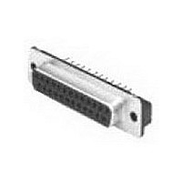
... This specification covers perform ance, tests and quality requirem ents for the following AMPLIMITE* printed circuit board m ounted connectors: ! HD-20 right angle front m etal shell for both standard tem perature processing and surface m ount com patible processing. ! HD-20 straight posted all plastic and front m etal shell. ...
Page 2
... Requirem ent Meets requirem ents of product drawing and applicable Application Specification. ELECTRICAL 15 m illiohm s m axim um initial illiohm s m axim um final. 5000 m egohm s m inim um initial. 1000 m egohm s m inim um final within 5 hours after testing. 1 kvac dielectric withstanding voltage inute hold illiam pere m axim um leakage current ...
Page 3
... Therm al shock. Hum idity-tem perature cycling. Tem perature life. Mixed flowing gas. Shall m eet visual requirem ents, show no physical dam age and shall m eet requirem ents of NOTE additional tests as specified in Test Sequence in Figure 2. Rev C Requirem ent See Note. Lbs Maxim um Size ...
Page 4
... Therm al shock Hum idity-tem perature cycling Tem perature life Mixed flowing gas (a) See paragraph 4.1.A. NOTE (b) Numbers indicate sequence in which tests are performed. Rev C Test Group ( Test Sequence (b) 1,9 1,6 1,6 1,3 1,5 3,7 2,5 2,5 2 Figure 2 108-40025 1,8 1,3 1,5 2,6 3 ...
Page 5
... Sam ple Selection Connector housings and contacts shall be prepared in accordance with applicable Instruction Sheets and shall be selected at random from current production. Test groups and 5 shall each consist ated connector pairs with no grounding indents and shall be m ounted to a printed circuit board. Test group 5 shall be m anufactured using 30 µin gold finish. Two wires shall be used in each crim p ...
Page 6
... Mounting and Clam ping Locations for Vibration and Physical Shock Rev C Figure 3 108-40025 ...
Page 7
... Multiplication Factor (F) from the above chart and m ultiply it tim es the Base Rated Current for a single circuit at the m axim um am bient operating tem perature as shown in Figure 4A. Rev C Figure 4A Current Carrying Capability W ire Size 1.0 .71 100% .30 .20 Figure 4B Current Rating 108-40025 28 .48 . ...