KIT34844AEPEVBE Freescale Semiconductor, KIT34844AEPEVBE Datasheet - Page 55
KIT34844AEPEVBE
Manufacturer Part Number
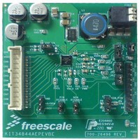
KIT34844AEPEVBE
Description
LED Lighting Development Kits IC, 10 CHANNEL LED BACKLIGHT
Manufacturer
Freescale Semiconductor
Datasheet
1.MC34844AEP.pdf
(62 pages)
Specifications of KIT34844AEPEVBE
Supply Voltage
12 V
Supply Current
2 uA
For Use With/related Products
34844A
Lead Free Status / RoHS Status
Lead free / RoHS Compliant


all external components related with the Boost converter and
Network compensation.
MOSFET and Diode should be taken into consideration.
current when the internal switch is off.
of the internal switch and winding resistance of the inductor.
maximum input current.
RMS current.
sense gain (CSG) and the Transconductance should be
taken in consideration.
amplifier gain (A
Analog Integrated Circuit Device Data
Freescale Semiconductor
The following formulas are intended for the calculation of
In order to calculate a Duty Cycle, the internal losses of the
The average input current depends directly to the output
Inductor
For calculating the Inductor we should consider the losses
It is important to look for an inductor rated at least for the
Input Capacitor
The input capacitor should handle at least the following
Output Capacitor
For the output capacitor selection the internal current
The CSG is the internal R
Irms
Iin
L
=
max
Cin
CSA
(
--------------------------------------------------------------------------------- -
Vin V
D
=
=
).
Iin
=
–
⎛
⎝
Iin
Vin
------------------------------------------------ -
2 L F
-------------------------------------------- -
Vout
avg
Vout
Iin
×
SW
avg
avg
+
×
SENSE
–
×
+
Vin
------------------------------------------------ -
2 L F
(
=
+
Vout Vin
(
×
×
V
Iin
V
------------ -
1 D
SW
Iout
r
D
D
–
×
×
avg
–
×
times the current sense
–
×
(
F
–
Vout Vin
V
Vin
SW
Vout
×
SW
SW
rw
COMPONENTS CALCULATION
×
)
–
)
⎞
⎠
) D
Vout
×
×
0.3
)
the Output capacitor, for a low output voltage ripple it is
recommended to use Ceramic capacitors that usually have
very low ESR. Since ceramic capacitor are expensive,
Electrolytic or Tantalum capacitors can be mixed with
ceramic capacitors to have a cheaper solution.
RMS current.
compensation is needed.
need to calculate all Boost Converter components.
Right Half Plane Zero to higher frequencies where it can’t
affect the overall loop significantly.
location of the Right half plane zero
R
SLOPE
The output voltage ripple (ΔV
The output capacitor should handle at least the following
Network Compensation
Since this Boost converter is current controlled, Type II
I order to calculate the Network Compensation, first we
For this type of compensations we need to push out the
The Crossover frequency must be set much lower than the
Since our system has a fixed Slope compensation set by
C
COMP1
, R
COMP
and C
ESR
Cout
Cout
should be fixed for all configurations.
Irms
COMP2
f
RHPZ
CSG
=
R
R
------------------------------------------------------------------- -
=
Cout
Comp
f
Comp
Cross
(
Vout
-------------------------------------------------------------- -
1 D
should be calculated as follows:
=
=
–
=
Vout
--------------------------------------- -
A
Iout 2 π L
×
=
CSA
Vout
=
×
Iout
) Vout CSG
5 G
5.6kohm
×
COMPONENTS CALCULATION
Δ
OUT
f
-------------- -
×
×
RHPZ
Vout F
×
×
5
×
×
(
R
M
) depends on the ESR of
1 D
×
(
Sense
–
1 D
×
------------ -
1 D
×
×
–
×
Iout L
D
–
)
SW
2
)
×
×
L
34844
55
Related parts for KIT34844AEPEVBE
Image
Part Number
Description
Manufacturer
Datasheet
Request
R

Part Number:
Description:
Manufacturer:
Freescale Semiconductor, Inc
Datasheet:
Part Number:
Description:
Manufacturer:
Freescale Semiconductor, Inc
Datasheet:
Part Number:
Description:
Manufacturer:
Freescale Semiconductor, Inc
Datasheet:
Part Number:
Description:
Manufacturer:
Freescale Semiconductor, Inc
Datasheet:
Part Number:
Description:
Manufacturer:
Freescale Semiconductor, Inc
Datasheet:
Part Number:
Description:
Manufacturer:
Freescale Semiconductor, Inc
Datasheet:
Part Number:
Description:
Manufacturer:
Freescale Semiconductor, Inc
Datasheet:
Part Number:
Description:
Manufacturer:
Freescale Semiconductor, Inc
Datasheet:
Part Number:
Description:
Manufacturer:
Freescale Semiconductor, Inc
Datasheet:
Part Number:
Description:
Manufacturer:
Freescale Semiconductor, Inc
Datasheet:
Part Number:
Description:
Manufacturer:
Freescale Semiconductor, Inc
Datasheet:
Part Number:
Description:
Manufacturer:
Freescale Semiconductor, Inc
Datasheet:
Part Number:
Description:
Manufacturer:
Freescale Semiconductor, Inc
Datasheet:
Part Number:
Description:
Manufacturer:
Freescale Semiconductor, Inc
Datasheet:
Part Number:
Description:
Manufacturer:
Freescale Semiconductor, Inc
Datasheet: