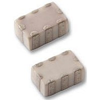
LFL211G89TC1A015 Murata, LFL211G89TC1A015 Datasheet - Page 8

LFL211G89TC1A015
Manufacturer Part Number
LFL211G89TC1A015
Description
FILTER, LOWPASS, 1.89GHZ
Manufacturer
Murata
Type
Chip Multilayer LC Filtersr
Datasheet
1.LFB185G78SGAB713.pdf
(17 pages)
Specifications of LFL211G89TC1A015
Bandpass Insertion Loss Max
0.47dB
Attenuation @ Reject Band Min
30dB
Filter Case
0805
No. Of Pins
8
Termination Type
SMD
Filter Type
Low Pass
Rohs Compliant
Yes
Frequency
1.89 GHz
Impedance
50 Ohms
Operating Temperature Range
- 40 C to + 85 C
Filter Terminals
SMD
Lead Free Status / RoHS Status
Lead free / RoHS Compliant
Lead Free Status / RoHS Status
Lead free / RoHS Compliant
!Note
• This PDF catalog is downloaded from the website of Murata Manufacturing co., ltd. Therefore, it’s specifications are subject to change or our products in it may be discontinued without advance notice. Please check with our
• This PDF catalog has only typical specifications because there is no space for detailed specifications. Therefore, please approve our product specifications or transact the approval sheet for product specifications before ordering.
sales representatives or product engineers before ordering.
o
LFL211G92TC1A060
LFL212G45TC1A007
LFL215G25TC1A156
LFL215G37TC1A210
LFL215G51TC1A149
LFL215G78TC1A155
LFH32942MRA1A517
LFD182G45DP3A299
LFD212G45DP3A140
LFD212G45DP3A151
LFD212G45DP3A188
LFD212G45DP4A189
LFH32_RA Series (1210)
Continued from the preceding page.
LFD18_DP Series
Part Number
Part Number
Part Number
Nominal Center
Nominal Center
Frequency (fo)
Frequency (fo)
(8)
0.1min.
5487.5 337.5MHz
All the technical data and information contained
herein are subject to change without prior notice.
5375 475.0MHz
5250 100.0MHz
5375 475.0MHz
(4)
A
2450 50.0MHz
0.55 0.15
0.65 0.15 0.30
Range[P1](f1)
5787.5
(MHz)
(MHz)
942.5
1920
2450
5250
5375
5512
Terminal of "NC" should not be fixed to any pattern.
All the technical data and Information contained
herein are subject to change without prior notice.
(1)
(7)
Frequency
0.45 0.15 1.0 0.2
Directional
Input mark
(MHz)
3.2 0.2
1.6 0.1
(2)
(6)
(1)
(3)
+0.10
-0.15
(3)
(5)
Bandwidth (BW)
Bandwidth (BW)
(2)
0.15 0.10
fo 100.0
fo 62.5
fo 17.5
fo 475
fo 363
(4)
0.4 0.2
(MHz)
(MHz)
fo 70
fo 50
5375 475.0MHz
2450 50.0MHz
2450 50.0MHz
2450 50.0MHz
2450 50.0MHz
(1) :
(2) :
(3) :
(4) :
A : Directional Input Mark
(*1) Higher Frequency Port
(*2) Common Port
(*3) Lower Frequency Port
Range[P2](f2)
Filters for Communication Equipment
Frequency
(1)(3)(5)(7) : NC
(2)(6) : GND
(4) : OUT
(8) : IN
GND
P1 (*1)
P3 (*2)
P2 (*3)
(MHz)
Chip Multilayer LC Filters (HPF)
0.6 0.1
1.5 0.15
Chip Multilayer Diplexers
0.50 max. (at 25 C)
0.70 max. (at 25 C)
0.70 max. (at 25 C)
0.70 max. (at 25 C)
0.70 max. (at 25 C)
0.6 max. (at 25 C)
0.5 max. (at 25 C)
for RF/Local
for RF/Local
Insertion Loss
(in mm)
Insertion Loss
(in mm)
in BW
in BW
(dB)
(dB)
0.60 max. (at 25 C)
0.65 max. (at 25 C)
0.75 max. (at 25 C)
0.75 max. (at 25 C)
0.5 max. (at 25 C)
Insertion Loss
[P1-P3](in f1)
(dB)
Attenuation (Absolute Value) I)
Attenuation (Absolute Value) I)
LFD21_DP Series
24 min. at 3335~3700MHz
27 min. at 2x(fo 50.0)MHz
30 min. at 2x(fo 62.5)MHz
24 min. at 2x(fo 100)MHz
30 min. at 2x(fo 475)MHz
30 min. at 2x(fo 363)MHz
4.5 min. at 480~600MHz
10
20
30
40
50
60
70
0
200
0.40 max. (at 25 C)
0.50 max. (at 25 C)
0.50 max. (at 25 C)
0.50 max. (at 25 C)
0.75 max. (at 25 C)
(dB)
(dB)
Insertion Loss
[P2-P3](in f2)
(dB)
Frequency Characteristics
0.2 0.15
All the technical data and information contained
herein are subject to change without prior notice.
Frequency Range (MHz)
(8)
0.3
( ) Common Port
(1)
(7)
+0.1
-0.15
700
Directional
Input mark
2.0 0.15
0.35 0.1
(2)
(6)
[P1-P3](in f2)
Attenuation (Absolute Value) II)
Attenuation (Absolute Value) II)
0.65 0.05
Attenuation
Continued on the following page.
20 min.
20 min.
20 min.
21 min.
17 min.
30 min. at 3700~3820MHz
30 min. at 3x(fo 50.0)MHz
20 min. at 3x(fo 62.5)MHz
19 min. at 3x(fo 100)MHz
20 min. at 3x(fo 475)MHz
20 min. at 3x(fo 363)MHz
(3)
(5)
(dB)
25 min. at 480MHz
(4)
0.3
+0.1
-0.2
(dB)
(dB)
(1)(2)(3)(5)(7) : GND
(4) : P1
(6) : P3 ( )
(8) : P2
[P2-P3](in f1)
1200
Attenuation
20 min.
20 min.
16 min.
17 min.
21 min.
0.95 0.1
0
10
20
30
40
50
60
70
(dB)
(in mm)
06.12.25
7


