ADIS16354/PCBZ Analog Devices Inc, ADIS16354/PCBZ Datasheet - Page 21
ADIS16354/PCBZ
Manufacturer Part Number
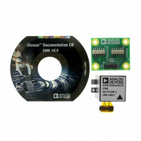
ADIS16354/PCBZ
Description
Triple Axis Gyro & Accelerometer Eval. Board
Manufacturer
Analog Devices Inc
Series
iMEMS®, iSensor™r
Datasheets
1.ADIS16350PCBZ.pdf
(2 pages)
2.ADIS16354PCBZ.pdf
(28 pages)
3.ADIS16354PCBZ.pdf
(2 pages)
Specifications of ADIS16354/PCBZ
Silicon Manufacturer
Analog Devices
Application Sub Type
Accelerometer / Gyroscope
Kit Application Type
Sensing - Motion / Vibration / Shock
Silicon Core Number
ADIS16354
Sensor Type
Accelerometer, Gyroscope, 3 Axis
Sensing Range
±1.7g, ±75°/sec, ±150°/sec, ±300°/sec
Interface
SPI Serial
Sensitivity
0.4625mg/LSB, 0.018°/LSB
Voltage - Supply
4.75 V ~ 5.25 V
Embedded
No
Utilized Ic / Part
ADIS16354
Lead Free Status / RoHS Status
Not applicable / Not applicable
For Use With
ADISUSBZ - KIT EVAL ADIS W/SOFTWARE USB
Lead Free Status / RoHS Status
Not applicable / Not applicable


Status Conditions
The STATUS register contains the following error condition
flags: alarm conditions, self-test status, overrange, SPI
communication failure, control register update failure, and
power supply range failure. See Table 31 and Table 32 for the
appropriate register access and bit assignment for each flag.
The bits assigned for checking power supply range and sensor
overrange automatically reset to zero when the error condition
no longer exists. The remaining error flag bits in the STATUS
register require a read to return them to zero. Note that a
STATUS register read clears all of the bits to zero. If any error
conditions remain, the bits revert to 1 during the next internal
output register update cycle.
Table 31. STATUS Register Definition
Address
0x3D, 0x3C
Table 32. STATUS Bit Descriptions
Bits
[15]
[14]
[13]
[12]
[11]
[10]
[9]
[8]
[7:6]
[5]
[4]
[3]
[2]
[1]
[0]
Description
X-axis accelerometer self-diagnostic error flag
Z-axis accelerometer self-diagnostic error flag
1 = failure, 0 = passing
1 = failure, 0 = passing
1 = failure, 0 = passing
1 = failure, 0 = passing
1 = failure, 0 = passing
X-axis gyroscope self-diagnostic error flag
1 = failure, 0 = passing
Alarm 2 status
1 = active, 0 = inactive
Alarm 1 status
1 = active, 0 = inactive
Self-test diagnostic error flag
1 = error condition, 0 = normal operation
Sensor overrange (any of the six)
1 = error condition, 0 = normal operation
SPI communications failure
1 = error condition, 0 = normal operation
Control register update failed
1 = error condition, 0 = normal operation
Power supply in range above 5.25 V
1 = above 5.25 V, 0 = below 5.25 V (normal)
Power supply below 4.75 V
1 = below 4.75 V, 0 = above 4.75 V (normal)
Z-axis gyroscope self-diagnostic error flag
Y-axis gyroscope self-diagnostic error flag
Not used
Y-axis accelerometer self-diagnostic error flag
Default
0x0000
Format
N/A
Access
Read only
Rev. A | Page 21 of 21
Alarms
The ADIS16354 provides two independent alarm options for
event detection. Event detections occur when output register
data meets the configured conditions. Configuration options
include the following:
The ALM_MAG1 register and the ALM_MAG2 register both
establish the threshold level for detecting events. These registers
take on the format of the source data and provide a bit for
establishing the greater than/less than comparison direction.
When making dynamic comparisons, the ALM_SMPL1 register
and the ALM_SMPL2 register establish the number of averages
taken for the source data as a reference for comparison. In this
configuration, each subsequent source data sample is subtracted
from the previous one, establishing an instantaneous delta. The
ALM_CTRL register controls the source data selection, static/
dynamic selection, filtering selection, and digital input/output
usage for the alarms.
The rate of change calculation is
where:
N
ALM_SMPL2.
y(n) is the sampled output data.
M
ALM_MAG2.
Y
•
•
•
•
•
C
DS
C
is the factor to compare with M
is the magnitude for comparison in ALM_MAG1 and
is the number of samples in ALM_SMPL1 and
All output data registers are available for monitoring as the
source data.
The source data can be filtered or unfiltered.
Comparisons can be static or dynamic (rate of change).
The threshold levels and times are configurable.
Comparison can be greater than or less than.
Y
Y
Rate
C
C
=
with
of
N
1
DS
change
M
n
N
∑
C
DS
=
according
1
y
(
alarm
n
+
) 1
−
is
to
y
determined
(
n
ALM_MAG1
)
C
.
by
comparing
/ALM_MAG2
ADIS16354
s
ettings.
Related parts for ADIS16354/PCBZ
Image
Part Number
Description
Manufacturer
Datasheet
Request
R

Part Number:
Description:
KIT EVAL FOR ADIS16354
Manufacturer:
Analog Devices Inc
Datasheet:

Part Number:
Description:
±1.7g Dual-Axis IMEMS Accelerometer Evaluation Board
Manufacturer:
Analog Devices Inc
Datasheet:
Part Number:
Description:
Inertial Sensor Evaluation System
Manufacturer:
Analog Devices Inc
Datasheet:
Part Number:
Description:
Manufacturer:
Analog Devices Inc
Datasheet:
Part Number:
Description:
Manufacturer:
Analog Devices Inc
Datasheet:
Part Number:
Description:
Manufacturer:
Analog Devices Inc
Datasheet:
Part Number:
Description:
Manufacturer:
Analog Devices Inc
Datasheet:
Part Number:
Description:
Manufacturer:
Analog Devices Inc
Datasheet:
Part Number:
Description:
Manufacturer:
Analog Devices Inc
Datasheet:
Part Number:
Description:
Manufacturer:
Analog Devices Inc
Datasheet:
Part Number:
Description:
Manufacturer:
Analog Devices Inc
Datasheet:
Part Number:
Description:
Manufacturer:
Analog Devices Inc
Datasheet:
Part Number:
Description:
Manufacturer:
Analog Devices Inc
Datasheet: