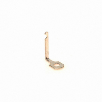
Y-141 Cinch Connectors, Y-141 Datasheet - Page 228

Y-141
Manufacturer Part Number
Y-141
Description
TERMINAL Y SOLDER 141 SERIES
Manufacturer
Cinch Connectors
Type
Terminal, Y-Solder, Barrier Blockr
Series
141r
Datasheet
1.Y-140.pdf
(282 pages)
Specifications of Y-141
Product
Tools & Accessories
Pitch
3.86 mm
Current Rating
20 A
Termination Style
Solder
Wire Gauge Max (awg)
14
Color
Black
Lead Free Status / RoHS Status
Lead free / RoHS Compliant
For Use With/related Products
141 Series
Number Of Positions
-
Lead Free Status / Rohs Status
Lead free / RoHS Compliant
Other names
CBB004
Y-141-P
Y141-P
Y-141-P
Y141-P
- Current page: 228 of 282
- Download datasheet (6Mb)
Dura-Con
High Reliability
Microedge Connectors
184 Contact Plug (Standard Insulated Wire)
Shell Polarization Kit
DNEBP0L1
DMEBP0L1
Mounting Hardware
Removable Jackscrew/Jackpost
Assembly
Order No.
Ordering Information
Consult factory if required.
Series Prefix
DMEB = Microedgeboard
DNEB = Microedgeboard, Narrow (184 Only)
Contact Spacing
1 = .050" (1.27mm) centers
128/184
2 = .100" (2.54mm) centers
64/92 (every other contact hole)
For other contact spacing accommodations, consult the factory.
No. of Contacts
128, 184
Contact Type
P = Pin
S = Socket
Wire Size in AWG
5 = 25 AWG Solid Copper
6 = 26 AWG Stranded Wire
S = Solder Cup
.250
.312
“L”
DNEB Narrow Only
DMEB Std. Width
Used On
DMEB 1-128 P 6 E 2 180
*Indicates Cinch std Option
.050" (1.27mm) Density
PC Board Mount
Metal Shell
Plug with Jackscrew
Standard Jackscrew/Jackpost Assembly
Key
5-37
* Narrow Version (DNEB) .250 Wide
Side View
Lead Length in Inches
Termination,
Color of Finish
*2 = Yellow
*4 = Gold-Plated (Solid Copper Wire Only)
*5 = Color Coded per MIL-Std. 681, System 1
Wire Type/Termination Style
C = Solid Copper
E = MIL-W-16878/4, 7 Strand
BS = PC Board (Coke Bottle)
BRA = PC Board Right-Angle (Formed to “A” Side)
BRB = PC Board Right-Angle (Formed to “B” Side)
W = PC Board (Claw Foot)
1 = White
3 = Tin-Plated
Call Toll Free: 1 (800) 323-9612
Receptacle with Jackscrew
L
5
Related parts for Y-141
Image
Part Number
Description
Manufacturer
Datasheet
Request
R

Part Number:
Description:
Standard Card Edge Connectors CINCH BLK CARD GUIDE
Manufacturer:
Cinch Connectors


