BZCT 120 BROYCE CONTROL, BZCT 120 Datasheet
BZCT 120
Manufacturer Part Number
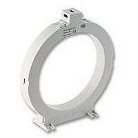
BZCT 120
Description
TOROID, 120MM (CORE BALANCE)
Manufacturer
BROYCE CONTROL
Datasheet
1.BZCT_070.pdf
(1 pages)
Specifications of BZCT 120
Current Max
1kA
Operating Temperature Max
60°C
Operating Temperature Min
-20°C
Supply Voltage Ac Max
720V
Mounting Type
Surface Mounting
Lead Free Status / RoHS Status
Lead free / RoHS Compliant
•
•
•
• FUNCTION DIAGRAM
Typical connection examples are shown below.
• INSTALLATION DO’s and DONT’s
•
• DIMENSIONS
Type: BZCT035, 070, 120 & 210
Circular Toroids
The information provided in this literature is believed to be accurate (subject to change without prior notice); however, use of such information shall be entirely at the user’s own risk.
BEFORE INSTALLATION, ISOLATE THE SUPPLY TO THE CABLES THAT ARE TO BE
PASSED THROUGH THE TOROID.
Installation of the toroid, along with the Earth Leakage Relay must be carried out in
accordance with the latest wiring practices and regulations.
L2
L3
Correct installation of the Earth Leakage Relay and toroid should ensure trouble free operation, in particular, if this document is followed.
L1
Telephone: +44 (0) 1902 773746 Facsimile: +44 (0) 1902 420639 Email: sales@broycecontrol.com Web: http://www.broycecontrol.com
N
E
INSTALLATION NOTE
For use in conjunction with Broyce “Type A” Earth Leakage Relays
Designed to detect leakage current and transmit a proportional signal to an Earth
Leakage Relay
Surface mounting with 4 fixing slots (BZCT210 supplied with separate mounting feet)
Slim design
1.
2.
3.
4.
5.
6.
Always ensure the Earth conductor DOES NOT pass through the
As a rule, select a toroid that has an inside diameter which is twice that
Ensure the cable is central in the toroid.
Place the toroid on a straight section of cable, not near a bend.
Keep the cable and toroid away from intense magnetic fields from
DO NOT pass individual conductors through separate toroids, as shown
toroid. If it is unavoidable, the Earth must be routed back through
the toroid again and around, as shown in Fig.2 below.
or greater than the outsider diameter of the cable(s) to be passed
through.
nearby equipment.
in Fig. 3.
E
D
E
3-Phase, 4-wire
BZCT035
C.T.
C.T.
C.T.
C.T.
ELR
Supply
B
Aux.
Broyce Control Ltd., Pool Street, Wolverhampton, West Midlands WV2 4HN. England
E
3-Phase, 3-wire
C.T.
C.T.
C.T.
C.T.
E
D
Installation work must be carried
BZCT070, 120 & 210mm
ELR
out by qualified personnel.
Supply
Aux.
E
E
1-Phase, 2-wire
Fig. 1
1 2
N
3
B
C.T.
C.T.
C.T.
C.T.
ELR
Supply
Aux.
E
BZCT035
BZCT070
BZCT120
BZCT210
Dimensions in mm
• TECHNICAL SPECIFICATION
Size availability* and part
* internal diameter
Rated system voltage:
Insulation level:
Current ratio:
Maximum permissible
Minimum IΔn setting on
Distance between
Ambient temp:
Relative humidity:
Housing:
Mounting option:
Terminal conductor size: ≤ 2.5mm
Approvals:
Toroid
number:
current:
Earth Leakage Relay for
each type of toroid:
toroid and relay:
Type:
1 2
120
210
Fig.2
A∅
N
35
70
3
105
155
149
64
B
35mm ∅ (BZCT035)
70mm ∅ (BZCT070)
120mm ∅ (BZCT120)
210mm ∅ (BZCT210)
720VAC
3kVAC
1/1000
1kA continuous
5kA for 1.5Sec.
100kA for 0.05Sec.
0.03A - 35 and 70mm ∅
0.1A - 120mm ∅
0.3A - 210mm ∅
50 metres (max.)
-20 to +60°C
+95%
Grey ABS
Panel mount only using fixing slots provided (BZCT210
requires separate mounting feet as supplied)
≤ 1.5mm
CE Compliant.
Conforms to: IEC44-1, IEC185 & BS7676
117
170
304
74
C
2
2
solid
stranded
1
60*
40
40
40
D
*exc. mounting feet
Fig.3
2
20
20
20
30
E
145
32
53
80
F
BZCT-3-A
3
Weight
1300g
135g
265g
77g
Related parts for BZCT 120
Image
Part Number
Description
Manufacturer
Datasheet
Request
R

Part Number:
Description:
TOROID, 70MM (CORE BALANCE)
Manufacturer:
BROYCE CONTROL
Datasheet:

Part Number:
Description:
RELAY, CONDUCTIVE LEVEL CONTROL
Manufacturer:
BROYCE CONTROL
Datasheet:
Part Number:
Description:
RELAY, CONDUCTIVE LEVEL CONTROL, 230VAC
Manufacturer:
BROYCE CONTROL
Datasheet:

Part Number:
Description:
RELAY, THERMISTOR
Manufacturer:
BROYCE CONTROL
Datasheet:

Part Number:
Description:
TEMPERATURE CONTROLLER, PT100
Manufacturer:
BROYCE CONTROL
Datasheet:

Part Number:
Description:
RELAY, UNDER/OVER CURRENT
Manufacturer:
BROYCE CONTROL
Datasheet:

Part Number:
Description:
RELAY, MULTIFUNCTION, CURRENT
Manufacturer:
BROYCE CONTROL
Datasheet:
Part Number:
Description:
RELAY, 3PHASE ASYMMETRY, 400VAC
Manufacturer:
BROYCE CONTROL
Datasheet:
Part Number:
Description:
RELAY,EARTH LEAKAGE VARIABLE
Manufacturer:
BROYCE CONTROL
Datasheet:
Part Number:
Description:
RELAY,EARTH LEAKAGE VARIABLE PANEL
Manufacturer:
BROYCE CONTROL
Datasheet:

Part Number:
Description:
SWITCH, BASIC, TOP PIN PLUNGER
Manufacturer:
Honeywell Sensing and Control
Datasheet:

Part Number:
Description:
SWITCH, BASIC, TOP PIN PLUNGER
Manufacturer:
Honeywell Sensing and Control
Datasheet:

Part Number:
Description:
SWITCH, BASIC, TOP ROLLER PLUNGER
Manufacturer:
Honeywell Sensing and Control
Datasheet:

Part Number:
Description:
SWITCH, BASIC, TOP ROLLER LEVER
Manufacturer:
Honeywell Sensing and Control
Datasheet:

Part Number:
Description:
SWITCH, BASIC, 1WAY ROLLER LEVER
Manufacturer:
Honeywell Sensing and Control
Datasheet: