45LM58D BANNER ENGINEERING, 45LM58D Datasheet - Page 4
45LM58D
Manufacturer Part Number
45LM58D
Description
Timing Logic Module
Manufacturer
BANNER ENGINEERING
Datasheet
1.45LM58D.pdf
(6 pages)
Specifications of 45LM58D
Time Range
0.01s To 0.15s, 0.1s To 1.5s, 1s To 15s
Application
For timing logic functions
Function
Module, Logic
Logic Type
On⁄Off Delay
Technology
Photoelectric
Timing Adjustment
0.01 to 15 Sec.
Operating Temperature
–40°C to 70°C
Lead Free Status / Rohs Status
RoHS Exempt Product


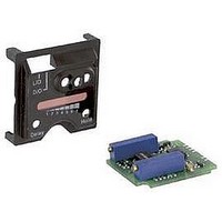
45LM Series Modules
The seven-element LED array, available on models 45LM58D and 45LMD, may be used
to measure the excess gain and contrast in any sensing situation and during sensor
installation and maintenance.
Excess gain is a measurement of the amount of light energy falling on the receiver of
a photoelectric sensor over and above the minimum amount necessary to operate the
sensor’s amplifier. Excess gain is expressed as a ratio:
The amplifier threshold is the point at which the sensor’s output switches. The Q45’s
threshold corresponds to the #3 level of the LED array. That is, when LEDs #1 through
#3 are lit, the excess gain of the received light signal is about “1x.”
The table at right (Figure 3) shows how excess gain relates to the LED array indicator.
Contrast is the ratio of the amount of light falling on the receiver in the “light” state
as compared to the “dark” state. Contrast is also referred to as “light-to-dark ratio.”
Optimizing the contrast in any sensing situation will increase the reliability of the
sensing system. Contrast may be calculated if excess gain values are known for both
the light and dark conditions:
To determine the contrast for any sensing application, present both the “light” and
“dark” conditions to the Q45, and read the signal for each. Take the ratio of the two
numbers (from Figure 3) that correspond to the highest LED numbers registered for
the “light” and “dark” conditions.
For example, if LEDs #1 through #6 come ON in the “light” condition and LEDs #1 and
#2 come ON in the “dark” condition, the contrast (referring to Figure 3) is calculated as
follows:
This value is expressed as “12:1” or “twelve-to-one.”
The best sensor adjustment will cause all seven LEDs to come ON for the “light”
condition, and will cause no LEDs to come ON in the “dark” condition. In this situation
(such as an application in which a box breaks the beam of an opposed mode emitter
and receiver):
Of course, it is not always possible to adjust a sensor to maintain this much contrast.
However, it is important to always adjust a sensor for the greatest amount of contrast
possible for any sensing situation. The LED signal strength indicator array makes this
easy. Figure 4 gives general guidelines for contrast values.
4
P/N 63416 rev. A
Excess gain (E.G.) = light energy falling on receiver
Contrast is greater than 8x = 32:1
Measuring Excess Gain and Contrast
Contrast
Contrast
=
= 6x = 12
Excess gain (light condition)
Excess gain (dark condition)
0.5x
0.25x
amplifier threshold
Banner Engineering Corp.
www.bannerengineering.com • Tel: 763.544.3164
Figure 3. The 7-segment LED array and its
Figure 4. Contrast values and corresponding
1.2 or
less
1.2 to 2
2 to 3
3 to 10
10 or
greater
Contrast
LED Number
Ratio
#1
#2
#3
#4
#5
#6
#7
corresponding excess gain values
guidelines
1 2 3
Unreliable. Use an
alternative sensing scheme.
Poor contrast. Minor
sensing system variables
will affect sensing reliability.
Low contrast. Sensing
environment must remain
perfectly clean and all other
sensing variables must
remain stable.
Good contrast. Minor
sensing system variables
will not affect sensing
reliability.
Excellent contrast. Sensing
should remain reliable as
long as the sensing system
has enough excess gain for
operation.
Recommendation
•
Minneapolis, MN U.S.A.
4 5 6
Approximate Gain
0.25x
7
0.5x
1.0x
2.0x
4.0x
6.0x
8.0x
Related parts for 45LM58D
Image
Part Number
Description
Manufacturer
Datasheet
Request
R

Part Number:
Description:
Photoelectric Sensor
Manufacturer:
BANNER ENGINEERING
Datasheet:

Part Number:
Description:
Photoelectric Sensor
Manufacturer:
BANNER ENGINEERING
Datasheet:

Part Number:
Description:
LEDIR70XD4-XM-81039 MAX INTENS STROBE ONLY NO BANNER MARKS
Manufacturer:
BANNER ENGINEERING
Part Number:
Description:
M18SP6DL-72225 LABELED MOELLER NO BANNER MARKINGS BULK PACK
Manufacturer:
BANNER ENGINEERING
Part Number:
Description:
M18SP6DLQ-72226 LABLED MOELLER NO BANNER MARKINGS BULK PACK
Manufacturer:
BANNER ENGINEERING
Part Number:
Description:
M18SP6L-72223 LABELED MOELLER NO BANNER MARKINGS BULK PACK
Manufacturer:
BANNER ENGINEERING
Part Number:
Description:
M18SP6LQ-72224 LABELED MOELLER NO BANNER MARKINGS BULK PACK
Manufacturer:
BANNER ENGINEERING
Part Number:
Description:
Photoelectric Sensor
Manufacturer:
BANNER ENGINEERING
Datasheet:

Part Number:
Description:
Programmable Indicator Light
Manufacturer:
BANNER ENGINEERING
Datasheet:
Part Number:
Description:
INDICATOR LED PANEL 50MM GRN/RED/YEL 30V
Manufacturer:
BANNER ENGINEERING
Datasheet:
Part Number:
Description:
Programmable Indicator Light
Manufacturer:
BANNER ENGINEERING
Datasheet: