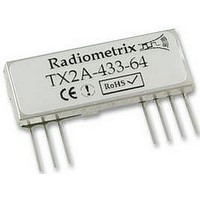
RX2A-433-64 RADIOMETRIX, RX2A-433-64 Datasheet - Page 6

RX2A-433-64
Manufacturer Part Number
RX2A-433-64
Description
RECEIVER, UHF, FM, RSSI
Manufacturer
RADIOMETRIX
Datasheet
1.RX2A-433-64.pdf
(11 pages)
Specifications of RX2A-433-64
Current Rating
12mA
Data Rate
64 Kbps
External Depth
4.5mm
External Length / Height
48mm
External Width
18mm
Frequency
433MHz
Operating Temperature Max
70°C
Operating Temperature Min
-20°C
Range
300
Lead Free Status / RoHS Status
Lead free / RoHS Compliant
Power supply requirement
The standard TX2A and the RX2A modules incorporate a built-in regulator which delivers a constant 2.8V
to the module circuitry when the external supply voltage is 2.85V or greater, with 40dB or more of supply
ripple rejection. This ensures constant performance up to the maximum permitted supply rail and
removes the need for external supply decoupling except in cases where the supply rail is extremely poor
(ripple/noise content >0.1Vp-p).
Note, however, that for supply voltages lower than 2.85V the regulator is effectively inoperative and
supply ripple rejection is considerably reduced. Under these conditions the ripple/noise on the supply rail
should be below 10mVp-p to avoid problems. If the quality of the supply is in doubt, it is recommended
that a 10 F low-ESR tantalum or similar capacitor be added between the module supply pin (Vcc) and
ground, together with a 10 series feed resistor between the Vcc pin and the supply rail.
The Enable pin allows the module to be turned on or off under logic control with a constant DC supply to
the Vcc pin. The module current in power-down mode is less than 1 A.
NOTE: If this facility is used, the logic control signal must have a slew rate of 40mV/ms or more. Slew
rates less than this value may cause erratic operation of the on-board regulator and therefore the module
itself.
The TX2A incorporates a low voltage shutoff circuit, which prevents any possibility of erratic operation by
disabling the RF output if the supply voltage drops below 2.2V (±5%). This feature is self-resetting, i.e.
restoring the supply to greater than 2.2V will immediately restore full RF output from the module.
TX2A modulation requirements
The module will produce the specified FM deviation with a TXD input to pin 7 of 2.5V amplitude, i.e. 0V
"low", 2.5V "high". Reducing the amplitude of the data input from this value (usually as a result of
reducing the supply voltage) reduces the transmitted FM deviation to typically ±25kHz at the lower
extreme of 2.2V. The receiver will cope with this quite happily and no significant degradation of link
performance should be observed as a result.
Where standard 2-level digital data is employed with a logic "low" level of 0V ±0.2V, the logic "high" level
applied to TXD may be any value between +2.5V and +3V for correct operation. However, if using multi-
level or analogue signalling the maximum positive excursion of the modulation applied to TXD must not
exceed +2.5V or waveform distortion will result. If the input waveform exceeds this level a resistive
potential divider should be used at the TXD input to reduce the waveform amplitude accordingly. This
input is high impedance (>100k ) and can usually be ignored when calculating required resistor values.
Received Signal Strength Indicator (RSSI)
The module incorporates a wide range RSSI which measures the strength of an incoming signal over a
range of approximately 60dB. This allows assessment of link quality and available margin and is useful
when performing range tests.
Please note that the actual RSSI voltage at any given RF input level varies somewhat between units. The
RSSI facility is intended as a relative indicator only - it is not designed to be, or suitable as, an accurate
and repeatable measure of absolute signal level or transmitter-receiver distance.
The output on pin 3 of the module has a standing DC bias of 0.15V-0.45V (0.25V typ.) with no signal,
rising to 0.9-1.3V (1.15V typ.) at maximum indication. The RSSI output source impedance is high (~50k )
and external loading should therefore be kept to a minimum.
To ensure a fast response the RSSI has limited internal decoupling of 1nF to ground. This may result in a
small amount of ripple on the DC output at pin 3 of the module. If this is a problem further decoupling
may be added at the expense of response speed, in the form of a capacitor from pin 3 to ground. For
example, adding 10nF here will increase RSSI response time from 100µs to around 1ms. The value of this
capacitor may be increased without limit.
Radiometrix Ltd, TX2A/RX2A Data Sheet
page 6


