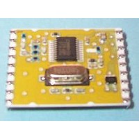
FM-RXQ1-433 RF Solutions, FM-RXQ1-433 Datasheet - Page 11

FM-RXQ1-433
Manufacturer Part Number
FM-RXQ1-433
Description
RADIO TRANSCEIVER RADIO TRANSCEIVER
Manufacturer
RF Solutions
Datasheet
1.FM-RXQ1-433.pdf
(12 pages)
Specifications of FM-RXQ1-433
Frequency
433.92MHZ
Temp, Op. Max
80(DEGREE C)
Temp, Op. Min
-20(DEGREE C)
DS0353-9 March ‘05
The design and positioning of the aerial is as crucial as the module performance itself in achieving a good
wireless system range. The following will assist the designer in maximising system performance.
The RF ground pin should be connected to a ground plane which should shield the aerial connection and the
PCB layout around the aerial track itself should be such as to give a 50 Ohm impedance. The aerial should be
kept as far away from sources of electrical interference as physically possible. The specified power supply
decoupling capacitors should be placed close to the module as possible and have direct connections to the
relevant pins.
The antenna ‘hot end’ should be kept clear of any objects, especially any metal as this can severely restrict the
efficiency of the antenna to receive power. Earth planes restricting the radiation path of the antenna will also
have the same effect.
The best range will be achieved with either a straight piece of wire, rod or PCB track @ ¼ wavelength (15.5cm
@ 433.92MHz). Increased range may be achieved if this ¼ wave antenna is placed perpendicular to and in
the middle of a solid earth plane measuring at least 16cm radius. In this case, the antenna should be
connected to the module using 50 Ohm coaxial cable and the PCB track layout tips given above should be
observed.
The Smart Radio Evaluation Kit provides a hardware platform to enable
fast development of Radio applications.
Supplied as a pair of boards, each can accept a variety of RF Modules
including transmitters, receivers and transceivers, an RS232 port is
incorporated for direct connection to a PC.
The boards may be used for a wide range of tasks from simple RS232
data transmission to integrated system development and is the ideal
platform for exploring the advantages of using the “Smart Comms” range
of ICs and radio modules.
This eliminates the need to construct hand-wired prototype boards, which
are rarely successful in creating a valid environment for the development
of radio systems. (prototyping board also contains large stray capacitance
values which has a detrimental effect on the RF connections).
Antenna Design
Smart Radio Evaluation Kit (Please see Datasheet DS605)
•
•
•
•
•
•
•
•
•
Hardware Platform for Radio Comms Development
Accepts Various RF Modules
RS232 Interface to PC
Supplied with RF600T Smart Comms Controller
Performs all Data Encryption for Reliable Data Comms.
Two Telemetry I/O Lines (addressed mode only)
Range Testing
Target Environment Testing
Antenna Evaluation
RF
Helical Antenna
17 turns equally spaced
∅ = 5mm (inside)
34mm @ 433MHz
FM N
©2005 Reg. No. 227 4001, ENGLAND
ARROW
B
AND
RF
Whip Antenna
T
RANSCEIVERS
Radio Modules and Antenna available
Separately.
Contents
•
•
•
•
•
15.5cm @ 433MHz
Two Eval Boards
Two RF600T Comms Controllers
Circuit diagrams
Two RS232 PC cables
Page 11
TRXQ1
RXQ1


