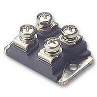
MMO 62-16IO6 IXYS SEMICONDUCTOR, MMO 62-16IO6 Datasheet - Page 2

MMO 62-16IO6
Manufacturer Part Number
MMO 62-16IO6
Description
THYRISTOR MODULE, 58A, 1600V
Manufacturer
IXYS SEMICONDUCTOR
Datasheet
1.MMO62-12IO6.pdf
(3 pages)
Specifications of MMO 62-16IO6
Peak Repetitive Off-state Voltage, Vdrm
1600V
Gate Trigger Current Max, Igt
100mA
Current It Av
25A
On State Rms Current It(rms)
54A
Peak Non Rep Surge Current Itsm 50hz
350A
Holding Current Max
RoHS Compliant
Symbol
I
V
V
r
V
I
V
I
I
I
t
t
R
R
d
d
a
© 2000 IXYS All rights reserved
R,
GT
GD
L
H
gd
q
T
miniBLOC, SOT-227 B
S
A
T
T0
GT
GD
thJC
thCH
I
M4 screws (4x) supplied
D
Test Conditions
T
I
For power-loss calculations only
V
V
T
T
I
T
T
I
T
V
per thyristor; DC current
per module
per thyristor; DC current
per module
Creeping distance on surface
Creepage distance in air
Max. allowable acceleration
T
G
G
VJ
VJ
VJ
VJ
VJ
VJ
D
D
R
= 0.3 A; di
= 0.3 A; di
= 6 V;
= 6 V;
= 100 V; dv/dt = 15 V/ms; V
= T
= 25°C; t
= 25°C; V
= 25°C; V
= T
= T
= 45 A; T
VJM
VJM
VJM
;
; I
; V
T
P
R
G
G
= 20 A, t
VJ
D
D
/dt = 0.3 A/ms
/dt = 0.3 A/ms
= 10 ms
= V
= 6 V; R
= 1/2 V
= 25°C
RRM
T
T
T
T
V
VJ
VJ
VJ
VJ
D
; V
= 2/3 V
= 25°C
= -40°C
= 25°C
= -40°C
P
DRM
= 200 ms; di/dt = -10 A/ms
GK
D
= V
= ¥
DRM
DRM
D
= 2/3 V
Dim.
A
B
C
D
E
F
G
H
J
K
L
M
N
O
P
Q
R
S
T
U
V
W
31.50
14.91
30.12
37.80
11.68
12.60
25.15
26.54
24.59
0.780
DRM
-0.05
7.80
4.09
4.09
4.09
8.92
0.76
1.98
4.95
3.94
4.72
3.30
Min.
Millimeter
Characteristic Values
31.88
15.11
30.30
38.20
12.22
12.85
25.42
26.90
25.07
0.830
Max.
8.20
4.29
4.29
4.29
9.60
0.84
2.13
5.97
4.42
4.85
4.57
0.1
typ.
typ.
typ.
£
£
£
£
£
£
£
£
£
£
£
-0.002
1.240
0.307
0.161
0.161
0.161
0.587
1.186
1.489
0.460
0.351
0.030
0.496
0.990
0.078
0.195
1.045
0.155
0.186
0.968
0.130
19.81
Min.
0.455
Inches
1.57
0.85
0.91
0.05
100
150
250
100
150
1.5
1.6
0.2
0.1
12
12
50
5
2
8
4
1.255
0.323
0.169
0.169
0.169
0.595
1.193
1.505
0.481
0.378
0.033
0.506
1.001
0.084
0.235
1.059
0.174
0.191
0.987
0.004
0.180
21.08
Max.
K/W
K/W
K/W
K/W
m/s
mW
mm
mm
mA
mA
mA
mA
mA
mA
ms
ms
V
V
V
V
V
2
Fig. 1 Gate trigger characteristics
Fig. 2 Gate trigger delay time
t
V
gd
1000
100
G
0.1
10
10
s
V
1
1
10
1
I
GD
1: I
2: I
3: I
, T
GT
GT
GT
VJ
, T
, T
, T
= 125°C
VJ
VJ
VJ
10
typ.
1
= 125°C
= 25°C
= -40°C
100
100
2
Limit
3
MMO 62
4: P
5: P
6: P
I
I
G
4
1000
G
GAV
GM
GM
T
VJ
=
= 10 W
mA
= 0.5 W
= 25°C
5 W
5
2 - 3
mA
1000
6


