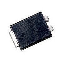
S6SRP Littelfuse Inc, S6SRP Datasheet - Page 6

S6SRP
Manufacturer Part Number
S6SRP
Description
SCR THYRISTOR, 510mA, 600V, DO-214
Manufacturer
Littelfuse Inc
Type
SCRr
Datasheet
1.S4010LS2.pdf
(12 pages)
Specifications of S6SRP
Peak Repetitive Off-state Voltage, Vdrm
600V
Gate Trigger Current Max, Igt
0.2mA
Current It Av
510mA
On State Rms Current It(rms)
800mA
Peak Non Rep Surge Current Itsm 50hz
16A
Repetitive Peak Off-state Volt
600V
Off-state Voltage
600V
Average On-state Current
510mA
Hold Current
5mA
Gate Trigger Current (max)
200uA
Gate Trigger Voltage (max)
800mV
Peak Reverse Gate Voltage
5V
Package Type
ComPAK
Peak Repeat Off Current
2uA
Peak Surge On-state Current (max)
20A
On State Voltage(max)
1.7@0.8AV
Mounting
Surface Mount
Pin Count
3
Operating Temp Range
-40C to 110C
Operating Temperature Classification
Industrial
Lead Free Status / RoHS Status
Lead free / RoHS Compliant
Sensitive SCRs
*Mounted on 1 cm
Electrical Isolation
Teccor’s isolated sensitive SCRs will withstand a minimum high
potential test of 2500 V ac rms from leads to mounting tab over
the device's operating temperature range. The following table
shows other standard and optional isolation ratings.
*UL Recognized File #E71639
**For 4000 V isolation, use “V” suffix in part number.
Figure E5.1 Maximum Allowable Case Temperature versus
http://www.littelfuse.com
+1 972-580-7777
Package Code
10.0 A
0.8 A
1.5 A
4.0 A
6.0 A
8.0 A
Type
130
120
110
100
90
80
70
60
50
0.1
V AC RMS
RMS On-state Current
2500
4000
0.2
2
copper foil surface; two-ounce copper foil
from Leads to Mounting Tab
0.3
75 [160]
50 [160]
TO-92
Electrical Isolation *
EC Series
RMS On-State Current [ I
E
0.4
0.5
CURRENT WAVEFORM: Sinusoidal
LOAD: Resistive or Inductive
CONDUCTION ANGLE: 180 ˚
CASE TEMPERATURE: Measured
as Shown on Dimensional Drawing
Compak
0.6
TO-220
4.0 [65]
T(RMS)
3.4
3.0
L
0.7
Optional **
JEDEC 2N Series
] – Amps
Standard
TO-220
0.8
Thermal Resistance (Steady State)
Type 2, 4, & 41
R
0.9
θJC
10 [100]
TO-202
F2
[R
1.0
θ JA
E5 - 6
] °C/W (TYPICAL)
Figure E5.2 Maximum Allowable Case Temperature versus
Figure E5.3 Maximum Allowable Case Temperature versus
Type 1 & 3
6.2 [80]
TO-202
4.3
3.9
3.4
F
130
120
110
100
90
80
70
60
50
RMS On-state Current
Average On-state Current
130
120
110
100
90
80
70
60
50
40
0
0
TCR22 Devices
Compak
EC Series
Average On-state Current [ I
0.1
0.5
4 A TO-251
and TO-252
60*
C
RMS On-state Current [ I
1.0
0.2
T106 and T107
Type 2 and 4
1.5
Compak
CURRENT WAVEFORM: Sinusoidal
LOAD: Resistive or Inductive
CONDUCTION ANGLE: 180˚
CASE TEMPERATURE: Measured
as Shown on Dimensional Drawing
CURRENT WAVEFORM: Sinusoidal
LOAD: Resistive or Inductive
CONDUCTION ANGLE: 180˚
CASE TEMPERATURE: Measured
as Shown on Dimensional Drawing
2.0
0.3
TO-252
D-Pak
1.45
3.0
1.8
1.5
D
T(RMS)
2.5
T(AV)
2.6
JEDEC 2N Series
Thyristor Product Catalog
0.4
] – Amps
T106 and T107
Type 1 and 3
] – Amps
3.0
©2004 Littelfuse, Inc.
3.5
0.5
0.51
4.0
TO-251
3.8 [85]
Data Sheets
V-Pak
1.72
2.4
2.1
0.6
V


