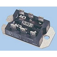
VS-P105W Vishay, VS-P105W Datasheet

VS-P105W
Specifications of VS-P105W
Available stocks
Related parts for VS-P105W
VS-P105W Summary of contents
Page 1
... CHARACTERISTICS 400 to 1200 - 40 to 125 /V , MAXIMUM V DRM RSM NON-REPETITIVE PEAK REVERSE VOLTAGE V 400 600 800 1000 1200 For technical questions, contact: indmodules@vishay.com P100 Series Vishay High Power Products /V RRM DRM VALUES UNITS 25 A 357 A 375 637 580 √s 2 6365 A ...
Page 2
... P100 Series Vishay High Power Products ON-STATE CONDUCTION PARAMETER SYMBOL Maximum DC output current at case temperature Maximum peak, one-cycle non-repetitive on-state or forward current 2 Maximum I t for fusing √t for fusing 2 Maximum I Maximum value of threshold voltage Maximum level value of on-state slope resistance Maximum on-state voltage drop ...
Page 3
... AC2 AC1 AC2 2 (-) (-) (+) Single phase hybrid bridge Single phase hybrid bridge doubler common cathode P10. P10.K P10.W P10.KW For technical questions, contact: indmodules@vishay.com P100 Series Vishay High Power Products VALUES Anode supply = 6 V resistive load 0.2 applied 2 VALUES - 40 to 125 2.24 ...
Page 4
... P100 Series Vishay High Power Products 180° ine Total Output Current (A) 93754_01a Fig Current Ratings Nomogram (1 Module Per Heatsink) 15 180° 120° 10 90° 60° 30° Average On-State Current (A) 93754_02 Fig On-State Power Loss Characteristics 20 DC 180° 15 120° ...
Page 5
... Instantaneous Gate Current (A) Fig Gate Characteristics LINKS TO RELATED DOCUMENTS For technical questions, contact: indmodules@vishay.com P100 Series Vishay High Power Products 400 Maximum non-repetitive urge current ver u pul e train duration. Control of 350 conduction may not be maintained. Initial T = 125 ° voltage reapplied ...
Page 6
... Vishay disclaims any and all liability arising out of the use or application of any product described herein or of any information provided herein to the maximum extent permitted by law. The product specifications do not expand or otherwise modify Vishay’ ...


