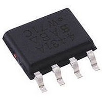
SRDA05-6.TET Semtech, SRDA05-6.TET Datasheet

SRDA05-6.TET
Specifications of SRDA05-6.TET
Related parts for SRDA05-6.TET
SRDA05-6.TET Summary of contents
Page 1
... The low inductance construction minimizes voltage overshoot during high current surges. Circuit Diagram Revision 2/25/10 SRDA3.3-6 and SRDA05-6 Low Capacitance TVS Diode Array Features Transient protection for high-speed data lines to IEC 61000-4-2 (ESD) ±15kV (air), ±8kV (contact) IEC 61000-4-4 (EFT) 40A (5/50ns) IEC 61000-4-5 (Lightning) 24A (8/20μ ...
Page 2
... PROTECTION PRODUCTS PROTECTION PRODUCTS Absolute Maximum Rating μ Electrical Characteristics (T= Note: (1) The SRDA3.3-6 is constructed using Semtech’s propri- etary EPD process technology. See applications section for more information. © 2010 Semtech Corp. SRDA3.3-6 and SRDA05 μ μ ° μ μ μ μ ...
Page 3
... PROTECTION PRODUCTS PROTECTION PRODUCTS Electrical Characteristics (continued © 2010 Semtech Corp. SRDA3.3-6 and SRDA05 ° μ μ μ μ www.semtech.com μ ...
Page 4
... Pulse Duration - t Pulse Waveform 110 100 Time (µs) Variation of Capacitance vs. Reverse Voltage -10 -12 - Reverse Voltage - V © 2010 Semtech Corp. SRDA3.3-6 and SRDA05-6 110 100 100 1000 (µs) p Clamping Voltage vs. Peak Pulse Current 16 Waveform 14 Parameters 8µ 20µ Forward Voltage vs. Forward Current ...
Page 5
... When the TVS is conducting current, it will exhibit a slight “snap-back” or negative resistance characteris- tics due to its structure. This point is defined on the © 2010 Semtech Corp. SRDA3.3-6 and SRDA05-6 Data Line Protection Using Internal TVS Diode as Reference ) the F EPD TVS IV Characteristic Curve ...
Page 6
... ESD suppression. The RailClamp’s integrated TVS diode helps to mitigate the effects of parasitic inductance in the power supply connection. During an ESD event, © 2010 Semtech Corp. SRDA3.3-6 and SRDA05-6 Figure 1 - “Rail-To-Rail” Protection Topology ) = 30V -9 Figure 2 - The Effects of Parasitic Inductance When ...
Page 7
... F(RailClamp) TVS This is given in the data sheet as the rated clamping voltage of the device. For an SRDA05-6 the typical clamping voltage is <16V at I =30A. The diodes PP internal to the RailClamp are low capacitance, fast switching devices that are rated to handle high tran- sient currents and maintain excellent forward voltage characteristics ...
Page 8
... REFERENCE JEDEC STD MS-012, VARIATION AA. Land Pattern - SO-8 (C) NOTES: 1. THIS LAND PATTERN IS FOR REFERENCE PURPOSES ONLY. CONSULT YOUR MANUFACTURING GROUP TO ENSURE YOUR COMPANY'S MANUFACTURING GUIDELINES ARE MET. 2. REFERENCE IPC-SM-782A, RLP NO. 300A. © 2010 Semtech Corp. SRDA3.3-6 and SRDA05 GAGE PLANE 0.25 L (L1) A DETAIL ...
Page 9
... PROTECTION PRODUCTS Marking SC YYWW SRDA3.3-6 PHIL SRDA3.3-6 YYWW = Date Code Tape and Reel Specification Contact Information © 2010 Semtech Corp. SRDA3.3-6 and SRDA05-6 Ordering Information YYWW SRDA05 PHIL SRDA05 ± ± ± Semtech Corporation Protection Products Division 200 Flynn Road, Camarillo, CA 93012 ...


