DIN3-165-277-L1 SUPERIOR ELECTRIC, DIN3-165-277-L1 Datasheet - Page 2
DIN3-165-277-L1
Manufacturer Part Number
DIN3-165-277-L1
Description
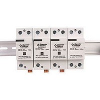
DIN Rail Mounted Surge Suppressor
Manufacturer
SUPERIOR ELECTRIC
Series
DIN3-165r
Datasheet
1.DIN3-165-120-L1.pdf
(2 pages)
Specifications of DIN3-165-277-L1
Suppressor Type
Data Line
Voltage Rating
277VAC
Operating Voltage Range
277VAC To 480VAC
Peak Surge Current
165kA
Connector Type
Screw Terminal
Frequency Max
64Hz


THE FOLLOWING IS INTENDED FOR QUALIFIED ELECTRICAL PERSONNEL
ONLY. COMPLETELY READ THESE INSTRUCTIONS BEFORE INSTALLATION. IT
IS THE FINAL RESPONSIBILITY OF THE INSTALLING ELECTRICIAN TO ENSURE
THAT ALL LOCAL CODES AND OTHER APPLICABLE SAFETY/ENVIRONMENTAL
CONDITIONS ARE MET AND THE UNIT IS CORRECTLY INSTALLED.
This manual provides guidelines for the proper installation of DIN3-165 Series units.
Proper product selection and compliance with these guidelines will help your new
suppression system provide years of reliable service. If installer’s are unsure about
the facility’s electrical confi guration or have other installation-related questions,
we recommend they consult with a master electrician or other qualifi ed electrical
professional.
REMOVE POWER FROM ELECTRICAL SYSTEM PRIOR TO INSTALLATION.
The DIN3-165 protectors are installed/connected in Parallel with the line and the
equipment to be protected
The DIN3-165 Series unit should be installed down stream of a 200 A maximum fuse
or breaker (see diagram). If pre-existing fuses or breakers are present, then the fusing or
breaker used for the DIN3-165 protector should have a lower rating in order to be properly
coordinated, as per applicable electrical regulatory standards. The Short Circuit current rating
for these DIN3-165 protectors are 25,000 Amps using a 50A Class J time delayed fuse.
213709-236 REV B
L1
L2
L3
N
Parallel Connection
The Importance of Correct Installation
Installation
Connection Methods
Disconnection
Indicator
Fuses
(200 A type gG)
Breaker
(200 A)
Delayed RDC Breaker
Inches (mm)
.
Example: 3 Ø, 4-Wire WYE, w/ground service confi guration
2.63 in (67mm)
2 in (51mm)
Dimensions
Ground
SAVE THESE INSTRUCTIONS!!
28 SPRING LANE • SUITE 3
FARMINGTON, CT 06032 USA
www.superiorelectric.com
Protected Installation
1.42 in (36mm)
<
T otal length
of the wires
0-2 ft. (0-0.5m)
Toward
Ground
Network
©2008 Superior Electric
Telephone and Fax Numbers
Telephone
Fax
Customer Service
Product Application
L1
L2
L3
N
“In-Line” Connection
t
F
V
DO NOT INSTALL THE DIN PROTECTOR IF MEASURED VOLTAGE EXCEEDS UNIT
RATINGS.
The DIN3-165 protector MUST BE mounted in an enclosure to assure personnel
safety from exposed terminals. Mechanically mount the DIN3-165 protector utilizing
customer supplied Din-Rail.
Wiring connection between the DIN3-165 protector and protected equipment should
be kept as short as possible. Superior Electric recommends that wire lengths be less
than 20 inches (0.5m). Wire should be straight and should not contain 90 degree
bends. If bends are required, they should be sweeping bends.
Unprotected cables should not be installed in parallel with the protected cables. This
will minimize coupling of inductively induced surges onto unprotected cables.
DIN3-165 protectors (except N-G protector) come standard with one remote monitoring
relay with “dry Form C contacts” per module. The contact can be used to drive several
different types of indicators such as a remote light indicator or an audible alarm. The
signal strength is (Vmax:250V rms, Imax: 2A). The connection to the remote signal is
through the screw terminals. Protector DIN3-164-480-L1 is provided with a “Form B dry
contact” per module.
The DIN3-165 protector is a maintenance free device. If the unit is subjected to a
prolonged over-voltage condition, an internal thermal element will activate, disconnecting
the DIN3-165 from the line. When the unit is no longer providing protection the window
on the front of the DIN3-165 becomes red and a replacement unit will be required.
Remote Signal
Maintenance
M
In
t
RDC Breaker
F
L
860-507-2025
860--507-2050
860-507-2025, Ext. 70782
860-507-2025, Ext. 72058
V
Delayed
Disconnection
Indicator
M
Out
t
Fuses
(200 A type gG)
Breaker
(200 A)
L1
L2
L3
F
N
Line Voltage Protector
V
C
M
Internal Protector Schematics
V : Heavy Duty Varistor
F : Thermal Fuse
C : Remote and Signal Contact
t : Thermal Disconnect
M: Monitor (Window)
Toll-Free (in USA and Canada only)
Telephone
Fax
Customer Service
Product Application
Ground
1-800-787-3532
1-800-821-1369
1-800-787-3532, Ext. 70782
1-800-787-3532, Ext. 72058
Neutral to Ground Protector
Protected Installation
In
N
<
T otal length
of the wires
0-2 ft. (0-0.5m)
Out
Printed in USA
Gas
Tube
Toward
Ground
Network
L1
L2
L3
N
Related parts for DIN3-165-277-L1
Image
Part Number
Description
Manufacturer
Datasheet
Request
R

Part Number:
Description:
DIN Rail Mounted Surge Suppressor
Manufacturer:
SUPERIOR ELECTRIC
Datasheet:
Part Number:
Description:
DIN Rail Mounted Surge Suppressor
Manufacturer:
SUPERIOR ELECTRIC
Datasheet:
Part Number:
Description:
DIN Rail Mounted Surge Suppressor
Manufacturer:
SUPERIOR ELECTRIC
Datasheet:

Part Number:
Description:
Replacement Brush For Superior Electric 126 Series Transformers
Manufacturer:
SUPERIOR ELECTRIC
Datasheet:

Part Number:
Description:
Variable Transformer
Manufacturer:
SUPERIOR ELECTRIC
Datasheet:

Part Number:
Description:
Variable Transformer
Manufacturer:
SUPERIOR ELECTRIC
Datasheet:
Part Number:
Description:
Variable Transformer
Manufacturer:
SUPERIOR ELECTRIC
Datasheet:

Part Number:
Description:
Variable Transformer
Manufacturer:
SUPERIOR ELECTRIC
Datasheet:

Part Number:
Description:
Variable Transformer
Manufacturer:
SUPERIOR ELECTRIC
Datasheet:

Part Number:
Description:
Variable Transformer
Manufacturer:
SUPERIOR ELECTRIC
Datasheet:
Part Number:
Description:
Variable Transformer
Manufacturer:
SUPERIOR ELECTRIC
Datasheet:
Part Number:
Description:
Variable Transformer
Manufacturer:
SUPERIOR ELECTRIC
Datasheet:
Part Number:
Description:
STABILINE Full Range Regulator Microprocessor Control, 1 Channel
Manufacturer:
SUPERIOR ELECTRIC
Part Number:
Description:
#21U TYPE 21-117 VARIAC 5 AMMP 120V INPUT TRANSISTOR
Manufacturer:
SUPERIOR ELECTRIC