CPM2C-10EDR Omron, CPM2C-10EDR Datasheet - Page 8
CPM2C-10EDR
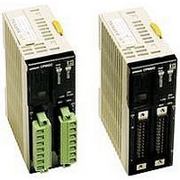
Manufacturer Part Number
CPM2C-10EDR
Description
Expansion I/O Modules
Manufacturer
Omron
Datasheet
1.CPM2C-10C1DR-D.pdf
(35 pages)
Specifications of CPM2C-10EDR
Output Type
Relay
External Width
33mm
Supply Voltage Max
24VDC
External Depth
65mm
Mounting Type
DIN Rail
External Height
90mm
Approval Bodies
UL, CSA, CE
Rohs Compliant
Yes
Lead Free Status / RoHS Status
Lead free / RoHS Compliant


J CPU CHARACTERISTICS
Notes are on the next page.
Item
Control method
I/O control method
Programming language
Instruction length
Instructions
Execution time
Program capacity
User data memory capacity
I/O
capacity
Clock function
Communications functions
Memory protection
(see notes 1 and 2)
Memory backup
(see notes 1 and 2)
Self-diagnostic functions
Program checks
Basic
i t
interrupts
High-
speed
speed
counter
Pulse output
Synchronized pulse control
Quick-response inputs
Q
Input time constant
(ON response time =
OFF response time)
/
it
t
p
CPU only
With Expansion
I/O Modules
Interrupt
processing
Interval timer
interrupts
High-speed
counter
Interrupt Inputs
(C
(Counter mode)
p
t
p
p
i
p
d )
10 I/O points
(relay/transistor outputs)
Stored program method
Cyclic scan with direct output (Immediate refreshing can be performed with IORF(97).)
Ladder diagram
1 step per instruction, 1 to 5 words per instruction
Basic instructions: 14
Special instructions: 105 instructions, 185 variations
Basic instructions: 0.64 µs (LD instruction)
Special instructions: 7.8 µs (MOV instruction)
4,096 words
2,048 words
10 points
170 points max.
Shows the year, month, day of the week, day, hour, minute, and
second. (Battery backup) CPUs with “C1” in the model number
have a built-in clock.
A CPM2C-CN111, CS1W-CN114 or CS1W-CN118 connecting cable is required to connect to the
CPM2C’s communications port. The communications port can be used as both a peripheral and
RS-232C port.
Peripheral port:
Supports Host Link, peripheral bus, no-protocol, or Programming Console connections.
RS-232C port:
Supports Host Link, no-protocol, 1:1 Slave Unit Link, 1:1 Master Unit Link, or 1:1 NT Link connections.
HR area, AR area, program contents, read/write DM area contents, and counter values are maintained
during power interruptions.
Flash memory:
Program, read-only DM area, and PC Setup
Memory backup:
The read/write DM area, HR area, AR area, and counter values are backed up
CPU with clock (battery): 2-year lifetime at 25_C
CPU without clock (capacitor): 10-day backup at 25_C
CPU without clock (lithium battery): 5-year lifetime at 25_C
CPU failure (watchdog timer), I/O bus error, battery error, and memory failure
No END instruction, programming errors (checked when operation is started)
2 interrupts
Shared by the external interrupt inputs (counter mode) and the quick-response inputs.
1 (Scheduled Interrupt Mode or Single Interrupt Mode)
One high-speed counter: 20 kHz single-phase or 5 kHz two-phase (linear count method)
Counter interrupt: 1 (set value comparison or set-value range comparison)
2 inputs
Shared by the external interrupt inputs and the quick-response inputs.
Two points with no acceleration/deceleration, 10 Hz to 10 kHz each, and no direction control.
One point with trapezoid acceleration/deceleration, 10 Hz to 10 kHz, and direction control.
Two points with variable duty-ratio outputs.
(Pulse outputs can be used with transistor outputs only, they cannot be used with relay outputs.)
One point:
A pulse output can be created by combining the high-speed counter with pulse outputs and multiplying
the frequency of the input pulses from the high-speed counter by a fixed factor.
(This output is possible with transistor outputs only, it cannot be used with relay outputs.)
2 inputs
Shared by the external interrupt inputs and the interrupt inputs (counter mode).
Min. input pulse width: 50 µs max.
Can be set for all input points.
(1 ms, 2 ms, 3 ms, 5 ms, 10 ms, 20 ms, 40 ms, or 80 ms)
Micro Programmable Controller
20 I/O points
(relay/transistor outputs)
20 points
180 points max.
4 interrupts
4 inputs
4 inputs
32 I/O points
(transistor outputs)
32 points
192 points max.
Not provided on CPUs with 32
I/O points.
4 interrupts
4 inputs
4 inputs
CPM2C
A--99
Related parts for CPM2C-10EDR
Image
Part Number
Description
Manufacturer
Datasheet
Request
R

Part Number:
Description:
CPM2C/SRM21w/DEVICENET,NPN OUT
Manufacturer:
Omron
Datasheet:

Part Number:
Description:
ACCESSORY; BACK UP BATTERY FOR CPM2C CPU UNIT
Manufacturer:
Omron Automation

Part Number:
Description:
Micro Programmable Logic Controller
Manufacturer:
Omron
Datasheet:

Part Number:
Description:
Micro Programmable Logic Controller
Manufacturer:
Omron
Datasheet:
Part Number:
Description:
Expansion I/O Modules
Manufacturer:
Omron
Datasheet:
Part Number:
Description:
Expansion I/O Modules
Manufacturer:
Omron
Datasheet:
Part Number:
Description:
Analog I/O Module
Manufacturer:
Omron
Datasheet:
Part Number:
Description:
Power Supply
Manufacturer:
Omron
Datasheet:
Part Number:
Description:
Temperature Sensor Input Module
Manufacturer:
Omron
Datasheet:
Part Number:
Description:
G6S-2GLow Signal Relay
Manufacturer:
Omron Corporation
Datasheet:
Part Number:
Description:
Compact, Low-cost, SSR Switching 5 to 20 A
Manufacturer:
Omron Corporation
Datasheet:
Part Number:
Description:
Manufacturer:
Omron Corporation
Datasheet: