CLSB4B1 Honeywell Sensing and Control, CLSB4B1 Datasheet - Page 3
CLSB4B1
Manufacturer Part Number
CLSB4B1
Description
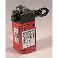
LIMIT CABLE PULL SWITCH, 200FT
Manufacturer
Honeywell Sensing and Control
Datasheet
1.CLSB4B.pdf
(6 pages)
Specifications of CLSB4B1
Contact Configuration
DPST-1NO / 1NC
Contact Current Ac Max
6A
Contact Current Dc Max
2.8A
Contact Voltage Ac Max
600V
Contact Voltage Dc Max
250V
Cable Span
66.6m
Circuitry
DPST-1NO/1NC
Lead Free Status / RoHS Status
Lead free / RoHS Compliant


Momentary Cable Pull Limit Switches: For Signaling Applications
TECHNICAL DATA CLS SERIES SPECIFICATIONS
Electrical
Rate thermal current
Rate insulation voltage
Impulse voltage
Contact resistance
Operating rating
UL/CSA
Mechanical
Protection class
Mechanical life
Temperature Range
Terminal identification
Head/housing material
CABLE PULL SWITCH
CHARACTERISTICS
Momentary Cable Pull Limit Switches are
offered with a black operating head and a
blue body. There is a choice of four different
conduit openings: 1/2-14 NPT, 20mm, PF
1/2, and PG13.5. Duplex switches have 3
standard conduit openings with two conduit
plugs provided.
All switches come with a 1NO auxiliary con-
tact as standard.
A66
Honeywell
Sensing and Control 1-800-537-6945 USA
I
U
U
AC15
DC13
A600/Q300
NEMA 1, 3, 4 and 13
10
–1 to 70 C (30 to 158 F)
Numbering to EN50013
Zinc die cast
th
i
imp
An additional auxiliary switch is also avail-
able in the Duplex. This auxiliary switch may
be configured as 1NO - 1NC direct acting,
2NO - 2NC snap action (monitoring only) or
1NO - 1NC with Smart Distributed System
output (monitoring only).
Neon and LED indicators are available. A
6 watt incandescent pilot light is available
on the Duplex for high visibility at long
distances.
25 milliohms
5
operations maximum
10 A
660 VAC/660 VDC
2.5 kV
U
U
U
U
U
600 V: I
240 V: I
120 V: I
250 V: I
24 V: I
2.8 A
1-815-235-6847 International 1-800-737-3360 Canada
1.2 A
3 A
6 A
0.27 A
SMART DISTRIBUTED SYSTEM OUTPUT
VERSION
The Smart Distributed System Output Ver-
sion provides Smart Distributed System
compatible switch status messaging. The
primary contact block (NC) must be wired to
the control current. The auxiliary contact
block has been replaced with the Smart
Distributed System circuitry.
Snap action contact blocks and the Smart
Distributed Output Version should be used
for monitoring only. These types of switches
should not be used in control circuits.
Related parts for CLSB4B1
Image
Part Number
Description
Manufacturer
Datasheet
Request
R

Part Number:
Description:
SERIES 942 SEPARATE COMPLETE SENSOR WITH HEAD AND CONTROL BOX, 3000 MM [118.0 IN] SCAN DISTANCE, TWO ANALOG OUTPUTS (0 VDC TO 10 VDC AND 4 MA TO 20 MA) , TWO SWITCHING OUTPUTS PNP AND DIGITAL LINK
Manufacturer:
Honeywell Sensing and Control
Part Number:
Description:
SERIES 942 SEPARATE COMPLETE SENSOR WITH HEAD AND CONTROL BOX, 900 MM [35.0 IN] SCAN DISTANCE, TWO ANALOG OUTPUTS (0 VDC TO 10 VDC AND 4 MA TO 20 MA) , TWO SWITCHING OUTPUTS PNP AND DIGITAL LINK
Manufacturer:
Honeywell Sensing and Control
Part Number:
Description:
SERIES 942 SEPARATE COMPLETE SENSOR WITH HEAD AND CONTROL BOX, 1500 MM [59.0 IN] SCAN DISTANCE, TWO ANALOG OUTPUTS (0 VDC TO 10 VDC AND 4 MA TO 20 MA) , TWO SWITCHING OUTPUTS PNP AND DIGITAL LINK
Manufacturer:
Honeywell Sensing and Control
Part Number:
Description:
SERIES 942 SEPARATE CONTROL BOX, 3000 MM [118.0 IN] SCAN DISTANCE, TWO ANALOG OUTPUTS (0 VDC TO 10 VDC AND 4 MA TO 20 MA) , TWO SWITCHING OUTPUTS PNP AND DIGITAL LINK, TO USE WITH 942 OR 947 SENSOR HE
Manufacturer:
Honeywell Sensing and Control
Part Number:
Description:
100FW SERIES, SHIELDED 3-WIRE DC SINKING (NPN), N.O. PROXIMITY SENSOR, 0.625 IN CYLINDRICAL HOUSING , 20 GA, MIL-W-16878/4 WIRE. NOMINAL SENSING DISTANCE OF 2,41 MM ±
Manufacturer:
Honeywell Sensing and Control
Part Number:
Description:
100FW SERIES, SHIELDED 3-WIRE DC SINKING (NPN), N.O. PROXIMITY SENSOR, 0.625 IN CYLINDRICAL HOUSING , CONNECTOR VERSION MATES WITH MS3116-10-6S. NOMINAL SENSING DISTANCE OF 2,41 MM ±
Manufacturer:
Honeywell Sensing and Control
Part Number:
Description:
HyCal Sensing Products
Manufacturer:
Honeywell Sensing and Control
Part Number:
Description:
200FW SERIES, SHIELDED 3-WIRE DC SINKING (NPN), N.O. PROXIMITY SENSOR, 0.625 IN CYLINDRICAL HOUSING , CONNECTOR VERSION MATES WITH MS3116-8-4S. NOMINAL SENSING DISTANCE OF 2,4 MM TO 11,4 MM [.09 IN
Manufacturer:
Honeywell Sensing and Control
Part Number:
Description:
FF-SRL SERIES, PRESENCE SENSING DEVICE INITIATION MODULE, 24 VDC
Manufacturer:
Honeywell Sensing and Control
Part Number:
Description:
HyCal Sensing Products
Manufacturer:
Honeywell Sensing and Control
Part Number:
Description:
HyCal Sensing Products
Manufacturer:
Honeywell Sensing and Control
Part Number:
Description:
HyCal Sensing Products
Manufacturer:
Honeywell Sensing and Control
Part Number:
Description:
SERIES 942 SEPARATE SENSOR HEAD, 1500 MM [59.0 IN] SCAN DISTANCE, STAINLESS STEEL M30, CONNECTOR, TO USE WITH 942-M0A CONTROL BOX
Manufacturer:
Honeywell Sensing and Control