N7E50-7516PG-20 3M, N7E50-7516PG-20 Datasheet - Page 4
N7E50-7516PG-20
Manufacturer Part Number
N7E50-7516PG-20
Description
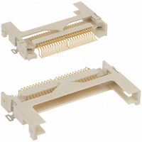
CF CARD HEADER TYPE I SMD
Manufacturer
3M
Series
7E50r
Type
Ir
Specifications of N7E50-7516PG-20
Card Type
Compact Flash - Type I
Number Of Positions
50
Connector Type
Connector
Insertion, Removal Method
Push In, Pull Out
Mounting Type
Surface Mount, Right Angle
Features
Board Guide, Card Guide
Height Above Board
0.261" (6.64mm)
Mounting Feature
Normal, Standard - Top
Contact Finish
Gold
Contact Finish Thickness
Flash
Product
Headers
Rohs Compliant
Yes
Lead Free Status / RoHS Status
Lead free / RoHS Compliant
Ejector Side
-
Lead Free Status / Rohs Status
Lead free / RoHS Compliant
Other names
05111165508
3M5438
4547452459421
54745245942
JE150339370
N7E50-7516PG-20
N7E507516PG20
3M5438
4547452459421
54745245942
JE150339370
N7E50-7516PG-20
N7E507516PG20
Available stocks
Company
Part Number
Manufacturer
Quantity
Price
Company:

Part Number:
N7E50-7516PG-20-WF
Manufacturer:
NAIS
Quantity:
1 179


3M
.100” × .100” Latch/Ejector, Straight and Right Angle
3
Electronic Solutions Division
Interconnect Solutions
http://www.3Mconnector.com
Blank = Std. Temp Gray (PBT) /(Blank or UB Pltg. Req’d.)
This spec sheet details our standard offering.
3M has several capabilities that can provide a part tailored to
your specific needs. Ask your 3M sales representative or
customer service for more details.
Use of snap-in style latch/ejectors in either short (N3XXX
X5XX) or long (N3XXX-X6XX) styles, installed or shipped
separately (the -5 & -6 snap-in latches are dimensional and
functional equivalents to the -2 & -3 roll pin latches) which
are also available separately with roll pins included. Refer to
chart below.
If ordering snap-in or roll pin style latches separately, please use the below chart
• Selective pin removal (ATA or other compatability)
• Wire wrap tails styles
Standard Temperature
(PBT)
High Temperature
(PCT)
High Temperature (PBT)
High Temperature (PPA)
Ordering Information
1 = 3 Wall, Right Angle Solder Tail
2 = 3 Wall, Straight Solder Tail
™
Shroud and Pin Configuration
N = High Temp Black (PCT)/(RB Plating Req’d)
Three-Wall Header
Part Customization
Short Latch
3505-2
N3505-2B
3505-30
N3505-30B
Long Latch
3505-3
N3505-3B
3505-31
N3505-31B
Latch Style
Roll Pin
Roll Pin
Snap-In
Snap-In
3M Part Number
2 = Short Roll PinLatch/Ejectors
3 = Long Roll Pin Latch/Ejectors
X3XXX - XXXX XX
(See Table 1)
Latch/Ejector System
Color
Gray
Black
Gray
Black
0 = No Latch/Ejector
Kinked Tail Detail:
Kink is located .05” below bottom surface of plastic.
External radius of kink toward part centerline.
Tail
02 = Solder Tail for .062 [1.57] Thick Board
K2= Kinked Solder Tails for .062 [1.57] Thick Board
03 = Solder Tails for .094 to .125 [2.39 to 3.18] Thick Board
Total Number
RB = 30 μ” Gold with Matte Tin Tails (App. E1 & C1 Apply)
Blank or UB = 30 μ” Gold with Sn/Pb Tails (App. E3 & C2 Apply)
Kinked Tail (K2 option) positions:
of Pins
2500 & 3000 Series Shrouded Header
10
14
16
20
24
26
30
34
36
40
50
60
64
For technical, sales or ordering information call
Tails Kinked
Number of
3M is a trademark of 3M Company.
4
4
4
4
4
4
4
4
4
4
4
4
4
11 12 49 50
11 12 53 54
3
3
3
3
3
3
5
7
7
7
7
Positions
Kinked
4
4
4
4
4
4
6
8
8
8
8
11 12
13 14
17 18
21 22
23 24
25 26
27 28
27 28
33 34
43 44
3000 Series
7
800-225-5373
8
Sheet 4 of 5
TS-0771-E
Related parts for N7E50-7516PG-20
Image
Part Number
Description
Manufacturer
Datasheet
Request
R

Part Number:
Description:
CF CARD HEADER TYPE I SMD INVRSE
Manufacturer:
3M
Datasheet:

Part Number:
Description:
CF CARD HEADER TYPE I SMD
Manufacturer:
3M
Datasheet:

Part Number:
Description:
CF CARD HEADER TYPE I SMD INVRSE
Manufacturer:
3M
Datasheet:

Part Number:
Description:
CF CARD HEADER TYPE II SMD
Manufacturer:
3M
Datasheet:

Part Number:
Description:
CF CARD HEADER TYPE II SMD INVTD
Manufacturer:
3M
Datasheet:

Part Number:
Description:
3M-MINI-CLAMP/PLUG/WMIC/2MM/3POS/TYPE A/ORANGE/3M LOGO
Manufacturer:
3M
Datasheet:
Part Number:
Description:
3M-MINI-CLAMP/PLUG/WMIC/2MM/4POS/TYPE A/YELLOW/3M LOGO
Manufacturer:
3M
Datasheet:
Part Number:
Description:
3M-MINI-CLAMP/PLUG/WMIC/2MM/4POS/TYPE A/ORANGE/3M LOGO
Manufacturer:
3M
Datasheet:
Part Number:
Description:
3M-MINI-CLAMP/SKT PANELMOUNT/WMIC/2MM/3POS/TYPE A/RED/3M LOGO
Manufacturer:
3M
Datasheet:
Part Number:
Description:
3M-MINI-CLAMP/SKT PANELMOUNT/WMIC/2MM/3POS/TYPE A/YELLOW/3M LO
Manufacturer:
3M
Datasheet:
Part Number:
Description:
3M-MINI-CLAMP/SKT/WMIC/2MM/3POS/TYPE A/ORANGE/3M LOGO
Manufacturer:
3M
Datasheet:
Part Number:
Description:
3M-MINI-CLAMP/SKT PANELMOUNT/WMIC/2MM/3POS/TYPE A/ORANGE/3M LO
Manufacturer:
3M
Datasheet:
Part Number:
Description:
3M-MINI-CLAMP/SKT PANELMOUNT/WMIC/2MM/4POS/TYPE A/RED/3M LOGO
Manufacturer:
3M
Datasheet:
Part Number:
Description:
3M-MINI-CLAMP/SKT/WMIC/2MM/4POS/TYPE A/YELLOW/3M LOGO
Manufacturer:
3M
Datasheet:
Part Number:
Description:
3M-MINI-CLAMP/SKT PANELMOUNT/WMIC/2MM/4POS/TYPE A/YELLOW/3M LO
Manufacturer:
3M
Datasheet: