SM312FP BANNER ENGINEERING, SM312FP Datasheet - Page 2
SM312FP
Manufacturer Part Number
SM312FP
Description
Photoelectric Sensor
Manufacturer
BANNER ENGINEERING
Type
DC Operated Sensorr
Specifications of SM312FP
Sensor Output
NPN/PNP
Sensor Input
Optical
Output Type
NPN/PNP, NO/NC
Supply Voltage Max
30VDC
Contact Current Max
150mA
Switch Terminals
Cable
Sensing Mode
Plastic Fiber
Brand/series
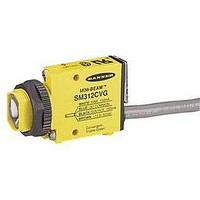
Mini-Beam®
Cable Type
4-Pin Euro QD
Current, Switching
150 mA
Function
Fiber Optic
Indicator
LED
Ip Rating
IP67
Light Source
Visible Red
Material, Casing
Thermoplastic Polyester (Housing)
Mounting Type
Threaded
Number Of Conductors
4
Output
NPN/PNP
Primary Type
Photoelectric
Standards
UL Recognized, CSA Certified, CE Marked, NEMA, IEC Approved
Technology
Photoelectric
Temperature, Operating
-20 to +70 °C
Termination
Cable
Time, Response
1 ms
Voltage, Supply
30 VDC
Output Current Max
150mA
Fiber Optic Sensor Type
DC Operated Sensor
Lead Free Status / Rohs Status
RoHS Exempt Product
For Use With
Banner glass fiberoptics


MINI-BEAM
The sensor’s Gain adjustment and Light/Dark Operate switch are located
under the gasketed acrylic cover. Loosen the screw to access these
adjustments and use a small screwdriver to adjust.
Gain adjustment:
Turn clockwise to increase gain (sensitivity); 15-turn Gain potentiometer is
clutched at both ends of travel.
Light/Dark operate selection:
• Turn switch fully clockwise for light operate (sensor outputs conduct
• Turn switch fully counterclockwise for dark operate (sensor outputs
Unterminated plastic fibers are designed to be cut by the user to
the length required for the application. To facilitate cutting, a
Banner model PFC-1 cutting device is supplied with the fiber. Cut
the fiber as follows:
1) Locate the “control end” of the fiber (the unfinished end).
2) Double-check the fiber length, and close the cutter until the fiber
3) Gently wipe the cut ends of the fiber with a clean, dry cloth to remove
1) Unlock the fiber gripper as shown in figure 3. If 0.25 mm or 0.5 mm core
2) Gently insert the prepared plastic fiber ends into the ports, as far as they
3) Slide the fiber gripper in to lock, as shown in figure 3.
page
MINI-BEAM Fiber Installation
when object is absent)
conduct when object is present)
Determine the length of fiber required for the application. If
using a bifurcated fiber, separate the two halves of the fiber at
least 2" beyond the fiber cutting location. Lift the top (blade) of
the cutter to open the cutting ports. Insert one of the control
ends through one of the cutting ports on the PFC-1 cutter so
that the excess fiber protrudes from the back of the cutter.
is cut. Using a different cutting port, cut the second control end
to the required length. To ensure a clean cut each time, do not
use a cutting port more than once.
any contamination. Do not use solvents or abrasives on any exposed
optical fiber.
fibers are being used, insert the small fiber adapter into the ports.
will go.
2
Unterminated Plastic Fiber Cutting Procedure
®
Plastic Fiber Optic Sensors –
MINI-BEAM Operation
Figure 2.
Use small ports for
fiber sizes:
Use large ports for
fiber sizes:
• 0.25 mm = (0.01")
• 0.5 mm = (0.02")
• 0.75 mm = (0.03")
• 1.0 mm = (0.04")
• 1.5 mm = (0.06")
Figure 1.
Figure 3.
PFC-1 plastic fiber cutter (supplied with fiber)
DC Models
light and pulses at a rate proportional to the
Sensor face
“AID” Indicator LED Lights when the
strength of the received light signal.
Banner Engineering Corp. • Minneapolis, U.S.A.
Website: http://www.baneng.com • Tel: 888.373.6767
sensor sees its own modulated
Plastic fiber
receiver port
Plastic fiber
emitter port
MINI-BEAM Plastic Fiber Optic sensor features
Installing fibers into the MINI-BEAM Plastic
Fiber Optic sensor
0.25 mm and
0.5 mm core
Adapter for:
fibers
Unlock
Lock
15 Turn
Sensitivity
Adjustment*
*Under acrylic cover
Lift to Open Ports
Light/Dark
Operate Switch*
Gasketed
Acrylic Cover
Trimmed fiber
control ends
Cutting Ports
4-Large
2-Small
Related parts for SM312FP
Image
Part Number
Description
Manufacturer
Datasheet
Request
R

Part Number:
Description:
Photoelectric Sensor
Manufacturer:
BANNER ENGINEERING
Datasheet:

Part Number:
Description:
Photoelectric Sensor
Manufacturer:
BANNER ENGINEERING
Datasheet:

Part Number:
Description:
LEDIR70XD4-XM-81039 MAX INTENS STROBE ONLY NO BANNER MARKS
Manufacturer:
BANNER ENGINEERING
Part Number:
Description:
M18SP6DL-72225 LABELED MOELLER NO BANNER MARKINGS BULK PACK
Manufacturer:
BANNER ENGINEERING
Part Number:
Description:
M18SP6DLQ-72226 LABLED MOELLER NO BANNER MARKINGS BULK PACK
Manufacturer:
BANNER ENGINEERING
Part Number:
Description:
M18SP6L-72223 LABELED MOELLER NO BANNER MARKINGS BULK PACK
Manufacturer:
BANNER ENGINEERING
Part Number:
Description:
M18SP6LQ-72224 LABELED MOELLER NO BANNER MARKINGS BULK PACK
Manufacturer:
BANNER ENGINEERING
Part Number:
Description:
P4D1-77908 P4 DRIVER GENERIC NO BANNER MARKINGS RESALE TO CUSTOMER
Manufacturer:
BANNER ENGINEERING
Part Number:
Description:
Photoelectric Sensor
Manufacturer:
BANNER ENGINEERING
Datasheet:

Part Number:
Description:
Programmable Indicator Light
Manufacturer:
BANNER ENGINEERING
Datasheet:
Part Number:
Description:
INDICATOR LED PANEL 50MM GRN/RED/YEL 30V
Manufacturer:
BANNER ENGINEERING
Datasheet:
Part Number:
Description:
Programmable Indicator Light
Manufacturer:
BANNER ENGINEERING
Datasheet: