110518 MAXON MOTORS, 110518 Datasheet
110518
Manufacturer Part Number
110518
Description
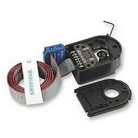
ENCODER, 3CHANNEL, 500 L, 8MM
Manufacturer
MAXON MOTORS
Datasheet
1.110518.pdf
(1 pages)
Specifications of 110518
Shaft Diameter
8mm
Svhc
No SVHC (15-Dec-2010)
Accessory Type
Encoder
Connector Type
Cable
No. Of Input Channels
3
Operating Temperature Range
0°C To +70°C
Supply
RoHS Compliant
No. Of Channels
3
Rohs Compliant
Yes
For Use With
Encoder 4205136
Encoder
May 2009 edition / subject to change
+ Motor
RE 50, 150 W
RE 50, 150 W
RE 50, 150 W
RE 65, 250 W
RE 65, 250 W
EC 32, 80 W*
EC 32, 80 W*
EC 32, 80 W*
EC 32, 80 W*
EC 40, 120 W*
EC 40, 120 W*
EC 40, 120 W*
EC-max 30, 40 W 170
EC-max 30, 40 W 170
EC-max 30, 40 W 170
EC-max 30, 40 W 170
EC-max 30, 40 W 170
EC-max 30, 40 W 170
EC-max 30, 60 W 171
EC-max 30, 60 W 171
EC-max 30, 60 W 171
EC-max 30, 60 W 171
EC-max 30, 60 W 171
EC-max 40, 70 W 172
EC-max 40, 70 W 172
EC-max 40, 70 W 172
EC-max 40, 70 W 172
EC-max 40, 120 W 173
EC-max 40, 120 W 173
EC-max 40, 120 W 173
EC-max 40, 120 W 173
* Pin Allocation siehe Page 270
Type
maxon Modular System
Technical Data
Supply voltage
Output signal
driver used:
Phase shift F
Signal rise time
(typically, at C
Signal fall time
(typically, at C
Index pulse width
Operating temperature range
Operating temperature range optional
Moment of inertia of code wheel
Max. angular acceleration
Output current per channel
Option
The index signal I is synchronised with channel A or B.
overall length
Stock program
Standard program
Special program (on request)
Counts per turn
Number of channels
Max. operating frequency (kHz)
Max. speed (rpm)
Shaft diameter (mm)
L
L
= 25 pF, R
= 25 pF, R
Page
83
83
83
84
84
156
156
156
156
157
157
157
1000 counts per turn, 2 channels
L
L
= 2.7 kW, 25°C)
= 2.7 kW, 25°C)
+ Gearhead
GP 52, 4 - 30 Nm
GP 52, 8 - 50 Nm
GP 81, 20 - 120 Nm
GP 32, 0.75 - 4.5 Nm 232
GP 32, 0.75 - 6.0 Nm 234/236
GP 32 S
GP 42, 3.0 - 15 Nm
GP 52, 4.0 - 30 Nm
GP 32, 1 - 6 Nm
GP 32, 1 - 6 Nm
GP 32 S
GP 32, 4.0 - 8.0 Nm
GP 32, 4.0 - 8.0 Nm
GP 42, 3 - 15 Nm
GP 42, 3 - 15 Nm
GP 42, 3 - 15 Nm
GP 42, 3 - 15 Nm
GP 52, 4 - 30 Nm
GP 52, 4 - 30 Nm
overall length
min. -20 mA, max. 20 mA
EIA Standard RS 422
250 000 rad s
-40 ... +100°C
90°e ± 45°e
5 V ± 10 %
DS26LS31
0 ... +70°C
£ 0.6 gcm
180 ns
40 ns
Page
243
245
246
251-253
240
243
236
236
237
237
241
241
241
241
244
244
90°e
-2
2
500 CPT, 3 Channels, with Line Driver RS
Pin Allocation for motor RE 75
+ Brake
AB 20
AB 20
AB 20
AB 20
AB 28
AB 28
AB 28
AB 28
Page
314
314
314
314
315
315
315
315
Flanged connector
Type SOURIAU 8GM-QL2-12P
1 V
2 N.C. (do not connect)
3 GND
4 N.C. (do not connect)
5 Channel I (Index)
6 Channel I
7 Channel B
8 Channel B
9 Channel A
10 Channel A
11 N.C. (do not connect)
12 N.C. (do not connect)
recommended cable plug
Type SOURIAU 8GM-DM2-12S
(metal, straight exit:
maxon Art. No. 2675.538) or
8G-V2-12S (plastic, 90° angle:
maxon Art. No. 2675.539)
CC
Overall length [mm] /
Order Number
110512
12000
100
500
3
3
110514
12000
101.7
123.7
100
78.4
62.6
84.6
500
3
4
see Gearhead
Connection example
Terminal resistance R = typical 100 W
Encoder
Line Driver
DS26LS31
Channel
Channel
Channel
Channel
Channel
Channel
110516
12000
121.4
111.4
151.4
100
88.4
81.4
500
3
6
110518
12000
128.7
157.3
500
100
3
8
maxon sensor
Line receiver
Recommended IC's:
- MC 3486
- SN 75175
- AM 26 LS 32
271
Related parts for 110518
Image
Part Number
Description
Manufacturer
Datasheet
Request
R

Part Number:
Description:
GEARHEAD, PLANETARY, 13MM, 67/1
Manufacturer:
MAXON MOTORS
Datasheet:
Part Number:
Description:
GEARHEAD, PLANETARY, 13MM, 275/1
Manufacturer:
MAXON MOTORS
Datasheet:
Part Number:
Description:
GEARHEAD, PLANETARY, 13MM, 1119/1
Manufacturer:
MAXON MOTORS
Datasheet:

Part Number:
Description:
GEARHEAD, PLANETARY, 19:1 RATIO
Manufacturer:
MAXON MOTORS
Datasheet:
Part Number:
Description:
GEARHEAD, PLANETARY, 370:1 RATIO
Manufacturer:
MAXON MOTORS
Datasheet:
Part Number:
Description:
GEARHEAD, PLANETARY, 1621:1 RATIO
Manufacturer:
MAXON MOTORS
Datasheet:

Part Number:
Description:
GEARHEAD, PLANETARY, 84:1 RATIO
Manufacturer:
MAXON MOTORS
Datasheet:
Part Number:
Description:
GEARHEAD, PLANETARY, 370:1 RATIO
Manufacturer:
MAXON MOTORS
Datasheet:
Part Number:
Description:
GEARHEAD, PLANETARY, 1621:1 RATIO
Manufacturer:
MAXON MOTORS
Datasheet:

Part Number:
Description:
GEARBOX, 18:1 RATIO
Manufacturer:
MAXON MOTORS
Datasheet:
Part Number:
Description:
GEARBOX, 30:1 RATIO
Manufacturer:
MAXON MOTORS
Datasheet:
Part Number:
Description:
GEARBOX, 60:1 RATIO
Manufacturer:
MAXON MOTORS
Datasheet:
Part Number:
Description:
GEARBOX, 100:1 RATIO
Manufacturer:
MAXON MOTORS
Datasheet:
Part Number:
Description:
GEARBOX, 200:1 RATIO
Manufacturer:
MAXON MOTORS
Datasheet:
Part Number:
Description:
GEARBOX, 500:1 RATIO
Manufacturer:
MAXON MOTORS
Datasheet: