FB1W-HW1B-V402R IDEC, FB1W-HW1B-V402R Datasheet - Page 11
FB1W-HW1B-V402R
Manufacturer Part Number
FB1W-HW1B-V402R
Description
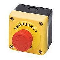
SWITCH, EMERGENCY STOP, 2NC, 600VAC
Manufacturer
IDEC
Datasheet
1.HW1A-B1-R.pdf
(61 pages)
Specifications of FB1W-HW1B-V402R
Contact Configuration
DPST-NC
Switch Operation
Pushlock Turn Reset
Contact Voltage Ac Nom
600V
Contact Voltage Dc Nom
220V
Contact Current Max
10A
Actuator Style
Mushroom
Lead Free Status / RoHS Status
Lead free / RoHS Compliant


510
Contacts
Operator Only (Red)
Operator Only (Yellow)
1NO
1NC
1NO-1NC
2NC
2NO
Contacts
1NO-1NC
2NC
2NC (with push-on
illumination)
1NO-1NC (with push-on
illumination )
1. * Available in Red only.
2. † Available in red or yellow. Insert color code in place of j (R: Red, Y: Yellow).
3. In place of l, specify Full Voltage Code.
4. With single unit construction, the positive action contacts are integrated in the body of the switch. This provides an extra
5. In the illuminated version, the light is independent of the switch action (except push-on LED model).
6. For accessories, see page 549.
7. For dimensions, see page 551.
8. For nameplates and shrouds, see page 550.
9. For contact assembly part numbers, see page 550.
10. All HW Series E-Stop operators include non-removable color caps.
11. All HW series E-Stops comply with EN418, the IEC “E-Stop Addendum to the Low Voltage Directive,” this includes “tamper
12. All HW series E-Stop switches comply with SEMI S2 standards.
13. All assembled part numbers in catalog include standard fingersafe (HW-F...) contacts.
14. Assembled units with spring-up terminals (HW-G...) can be ordered by removing an “F” from the part number (Ex. HW1B-
15. Units with exposed screw terminals (HW-C...) must be ordered as sub-components.
16. Additional contact configurations available (up to 6 total contacts).
degree of safety and reliability for critical emergency stop functions.
proof” operation whereby a change of contact state is not possible by “teasing” or “floating” the operator.
M1F11-R becomes HW1B-M111-R).
ø22mm - HW Series
Plastic Bezel
HW1B-Y2R
HW1B-Y2Y
HW1B-Y2F10-j†
HW1B-Y2F01-j†
HW1B-Y2F11-j†
HW1B-Y2F02-j†
HW1B-Y2F20-j†
LED
HW1E-LV4F11QD-R-l
HW1E-LV4F02QD-R-l
HW1E-TV4F02QD-R-l
HW1E-TV4F11QD-R-l
Unibody Illuminated E-Stops*
ø40mm Head Push–Pull
Push Pull & Unibody E-Stop Pushbuttons (Assembled)
Metal Bezel
HW4B-Y2R
HW4B-Y2Y
HW4B-Y2F10-j†
HW4B-Y2F01-j†
HW4B-Y2F11-j†
HW4B-Y2F02-j†
HW4B-Y2F20-j†
Incandescent
HW1E-LV4F11Q-R-l
HW1E-LV4F02Q-R-l
HW1E-TV4F11Q-R-l
HW1E-TV4F02Q-R-l
www.idec.com
Contacts
1NO-1NC
2NC
1NO-2NC
l Full Voltage Code
Voltage
6VAC/DC
12VAC/DC
24VAC/DC
120V AC*
240V AC*
*LED only.
Oiltight Switches & Pilot Devices
Code
6V
12V
24V
120V
240V
ø40mm Unibody Pushlock Turn Reset*
Plastic Bezel
HW1E-BV4F11-R
HW1E-BV4F02-R
HW1E-BV412R-TK2093-1
Terminal Numbering
(Unibody only)
Models
1NO-1NC NO = 13/14, NC = 11/12
2NC
HW1E-L
HW1E-T
Terminal Number
NC = 11/12, NC = 21/22
Lamp + = X2, Lamp - = X1
Related parts for FB1W-HW1B-V402R
Image
Part Number
Description
Manufacturer
Datasheet
Request
R

Part Number:
Description:
SWITCH, EMERGENCY STOP, 1NO/1NC, 600VAC
Manufacturer:
IDEC
Datasheet:

Part Number:
Description:
SWITCH; WITH ENCLOSURE; 40MM; EMO PUSHLOCK; TURN RESET; PLASTIC; 1 NC/ 1NO
Manufacturer:
IDEC Corporation
Datasheet:
Part Number:
Description:
SWITCH; WITH ENCLOSURE; 40MM PUSH PULL RESET; PLASTIC; 2 NC
Manufacturer:
IDEC Corporation
Datasheet:
Part Number:
Description:
SWITCH; WITH ENCLOSURE; 40MM; EMO PUSHLOCK; TURN RESET; PLASTIC; 2 NC
Manufacturer:
IDEC Corporation
Datasheet:
Part Number:
Description:
SWITCH; WITH ENCLOSURE; 29MM PUSHLOCK; TURN RESET; PLASTIC; 2 NC
Manufacturer:
IDEC Corporation
Datasheet:
Part Number:
Description:
SWITCH; WITH ENCLOSURE; 40MM PUSHLOCK; KEY RESET; PLASTIC; 1 NC/ 1NO
Manufacturer:
IDEC Corporation
Datasheet:
Part Number:
Description:
SWITCH; WITH ENCLOSURE; 29MM PUSHLOCK; TURN RESET; PLASTIC; 1 NC/ 1NO
Manufacturer:
IDEC Corporation
Datasheet:
Part Number:
Description:
Cable; Between IDEC MicroSmart (port 1 or 2) and HG2F/3F/4F; 5 ft.
Manufacturer:
IDEC Corporation
Datasheet:
Part Number:
Description:
Cable; Between IDEC Micro^3C/ONC/MicroSmart (port 2) PLCs and HG2F/3F/4F; 5 ft.
Manufacturer:
IDEC Corporation
Datasheet:
Part Number:
Description:
Connector: Wire to Board Connector: M: 24: 2: PRESS
Manufacturer:
Sullins Electronics
Datasheet:
Part Number:
Description:
Semiconductors and Electronic Components 1971
Manufacturer:
General Instrument
Part Number:
Description:
COMPOUND TRANSISTOR
Manufacturer:
NEC [NEC]
Datasheet:
Part Number:
Description:
INDICATOR INCANDESCENT LAMP, GREEN
Manufacturer:
IDEC
Datasheet:

Part Number:
Description:
LAMP, INDICATOR, INCAND, AMB
Manufacturer:
IDEC
Datasheet: