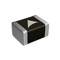
B59641A0125A062 EPCOS Inc, B59641A0125A062 Datasheet - Page 20

B59641A0125A062
Manufacturer Part Number
B59641A0125A062
Description
THERMISTOR PTC 470OHM 125DEG0603
Manufacturer
EPCOS Inc
Series
SuperioRr
Specifications of B59641A0125A062
Package / Case
0603 (1608 Metric)
Resistance In Ohms @ 25°c
470
Resistance Tolerance
±50%
Operating Temperature
-40°C ~ 125°C
Mounting Type
Surface Mount
Resistance
470 Ohms
Tolerance
50 %
Termination Style
SMD/SMT
Operating Temperature Range
- 40 C to + 125 C
Dimensions
0.8 mm W x 1.6 mm L x 0.8 mm H
Voltage
32 Volts
Thermistor Type
PTC
Thermistor Case Style
0603
No. Of Pins
2
Rohs Compliant
Yes
Lead Free Status / RoHS Status
Lead free / RoHS Compliant
Power - Max
-
Lead Free Status / Rohs Status
Lead free / RoHS Compliant
Other names
495-4307-2
Available stocks
Company
Part Number
Manufacturer
Quantity
Price
Company:
Part Number:
B59641A0125A062
Manufacturer:
EPCOS
Quantity:
80 000
Part Number:
B59641A0125A062
Manufacturer:
EPCOS/爱普科斯
Quantity:
20 000
Mounting instructions
1
1.1
Leaded PTC thermistors follow the solderability requirements of IEC 60068-2-20.
During soldering, care must be taken that the thermistors are not damaged by excessive heat.
The following maximum temperatures, maximum time spans and minimum distances have to be
observed:
Solderability
Resistance to
soldering heat
Distance to thermistor has to be 6 mm. Under more severe soldering conditions the resistance
may change. Soldering conditions for wave soldering are given in chapter 1.4.1.
1.2
In case of PTC thermistors without leads, soldering is restricted to devices which are provided
with a solderable metallization. The temperature shock caused by the application of hot solder
may produce fine cracks in the ceramic, resulting in changes in resistance.
In addition, soldering methods should be employed which permit short soldering times.
Soldering conditions for wave soldering are given in chapter 1.4.1.
1.3
The notes on soldering leadless thermistors also apply to the SMD versions (refer to
IEC 60068-2-58). Soldering conditions for wave soldering are given in chapter 1.4.1., for reflow
soldering in chapter 1.4.2.
1.3.1
(Sizes 0402, 0603, 0805, 1210)
As shown in the figure above, the terminations consists of three metallic layers. A primary chrome
layer provides for good electrical contact. "Leaching" is prevented by a nickel barrier layer. The
outer tin coating prevents corrosion of the nickel and ensures good component solderability.
Please read Cautions and warnings and
Important notes at the end of this document.
Sensors
Limit temperature sensors, EIA sizes 0402, 0603 and 0805
Soldering
Leaded PTC thermistors
Leadless PTC thermistors
SMD PTC thermistors
Chrome/nickel/tin terminations
Solder containing lead
(SnPb 60/40)
Solder bath temperature 230 C
Soldering time 3 s
Soldering iron temperature 350 C
Soldering time 3 s
Page 20 of 32
Lead-free solder
(Sn96.5Ag3Cu0.5)
Solder bath temperature 245 C
Soldering time 3 s
Solder bath temperature 260 C
Soldering time 10 s
Superior series


