EL7900ILCZ-T7 Intersil, EL7900ILCZ-T7 Datasheet - Page 5
EL7900ILCZ-T7
Manufacturer Part Number
EL7900ILCZ-T7
Description
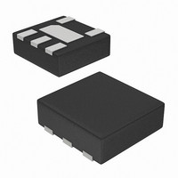
IC PHOTO DETECTOR AMBIENT 5-DFN
Manufacturer
Intersil
Datasheet
1.EL7900ILCZ-EVALZ.pdf
(8 pages)
Specifications of EL7900ILCZ-T7
Wavelength
550nm
Output Type
Current
Package / Case
5-ODFN
Rohs Compliant
Yes
Lead Free Status / RoHS Status
Lead free / RoHS Compliant
Other names
EL7900ILCZ-T7
Available stocks
Company
Part Number
Manufacturer
Quantity
Price
Company:

Part Number:
EL7900ILCZ-T7
Manufacturer:
TI
Quantity:
1 000


Application Information
Product Description
The EL7900 is a light-to-current optical sensor combining
photodiodes and current amplifiers on a single monolithic IC.
The photodiodes are temperature-compensated and their
spectrum resembles the human eye response. The output
current is directly proportional to the intensity of light falling
on the photodiodes. For 100lux of input fluorescent light, the
EL7900 has an output current of 60µA.
The EL7900 is housed in an ultra-compact surface mount
clear plastic package.
Light-to-Current and Voltage Conversion
The EL7900 has a responsiveness that is directly
proportional to the intensity of light intercepted by the
photodiodes. Although the conversion rate varies depending
on the light sources (fluorescent light, incandescent light or
direct sunlight), in general for a fluorescent light, the light-to-
current conversion is:
Here, I
input light in lux.
For some applications, a load resistor is added between the
output and the ground as shown in Figure 1. The output
voltage can be expressed in Equation 2:
Here, V
the load resistor added. The compliance of the EL7900's
output circuit may result in premature saturation of the
output current and voltage when an excessively large
R
below the supply voltage as listed in V
Electrical Specifications table on page 2.
In order to have the linear relationship between the input
light and the output current and voltage, a proper resistor
value (i.e., gain) should be picked for a specific input light
range. The resistor value can be picked according to
Equation 3:
Here, V
specific input light range for an application. For example, an
indoor light ranges typically from 0lux to 1,000lux. A resistor
value of 4.5kΩ for 3V supply voltage can be used. For a
small light range, a large resistor value should be used to
achieve better sensitivity; for a large light range, a small
resistor value should be used to prevent non-linear output
current and voltage.
I
V
R
OUT
OUT
LOAD
LOAD
=
=
OUT
OUT
SUP
⎛
⎝
is used. The output compliance voltage is 300mV
=
I
------------------ -
100lux
OUT
60μA
(
-------------------------------------- -
V
is the output current in µA, and L
SUP
is the supply voltage, and L
is the output voltage and R
×
60μA
⎞
⎠
R
×
–
LOAD
0.3V
L
INPUT
)
=
×
⎛
⎝
-----------------------
L
------------------ -
100lux
100lux
RANGE
60μA
5
⎞
⎠
×
L
INPUT
O(MAX)
LOAD
RANGE
×
INPUT
R
is the value of
of the
LOAD
is the
is the
(EQ. 1)
(EQ. 2)
(EQ. 3)
EL7900
Resistor Output R
The resistor output, R
function of the device. The device converts light into current
then R
R
lux levels. The table below lists R
output swing for typical lux range levels. A careful balance of
dynamic swing and fast response has to be considered
when choosing R
smaller value R
slow down response time. For maximum dynamic range or
swing, choose a higher value R
output impedance of the device is considerably large.
Hence, the light-to-current conversion deviation because of
resistor loading is infinitesimal. The recommended maximum
R
The output current must never exceed 6mA. When using
load resistances less than 800Ω, care must be taken when
lux go as high as 10,000lux because the output current rises
above 6mA before reaching the device’s output compliance.
The output compliance of the device is 300mV below the
supply. The output current stops ramping when the output
voltage reaches voltage compliance.
Application Examples
The following examples present from fully automatic to fully
manual override implementations. These guidelines are
applicable to a wide variety of potential light control
applications. The EL7900 can be used to control the
brightness input of CCFL inverters. Likewise, it can interface
well with LED drivers. In each specific application, it is
important to recognize the target environment and its
ambient light conditions. The mechanical mounting of the
sensor, light aperture hole size and use of a light pipe or
bezel are critical in determining the response of the EL7900
for a given exposure of light.
The example in Figure 10 shows a fully automatic dimming
solution with no user interaction. Choose R
for any desired minimum brightness and slope. Choose C
to adjust response time and to filter 50/60Hz room lighting.
For example, suppose you wish to generate an output
voltage from 0.25V to 1.25V to drive the input of an LED
driver controller. The 0.25V represents the minimum LED
ILLUMINATION RANGE
LOAD
LOAD
TABLE 1. V
LOAD
0 to 10,000
0 to 1,000
can range from 10Ω to 10MΩ depending on the input
is 10MΩ.
0 to 200
0 to 500
0 to 10
(lux)
converts the output current to an output voltage.
DD
LOAD
LOAD
= 5V, MAXIMUM OUTPUT VOLTAGE = 4.7V
LOAD
to shunt stray capacitances that may
. For faster response, choose a
LOAD
, determines the voltage transfer
RLOAD
(kΩ)
39.2
15.7
0.78
783
7.8
LOAD
LOAD
Selection
. Although finite, the
values to maximize
1
CURRENT OUT
and R
September 18, 2009
0 to 6,000
0 to 120
0 to 300
0 to 600
0 to 6
(µA)
2
values
FN7377.8
1
Related parts for EL7900ILCZ-T7
Image
Part Number
Description
Manufacturer
Datasheet
Request
R

Part Number:
Description:
Intersil Corporation [CMOS Serial Controller Interface]
Manufacturer:
Intersil Corporation
Datasheet:
Part Number:
Description:
Manufacturer:
Intersil Corporation
Datasheet:
Part Number:
Description:
357-036-542-201 CARDEDGE 36POS DL .156 BLK LOPRO
Manufacturer:
Intersil Corporation
Datasheet:
Part Number:
Description:
1024-Word x 4-Bit LSI Static RAM
Manufacturer:
Intersil Corporation
Datasheet:
Part Number:
Description:
General Purpose NPN Transistor Arrays FN341.4
Manufacturer:
Intersil Corporation
Datasheet:
Part Number:
Description:
CMOS 16-Bit Microprocessor
Manufacturer:
Intersil Corporation
Datasheet:
Part Number:
Description:
Manufacturer:
Intersil Corporation
Datasheet:
Part Number:
Description:
Manufacturer:
Intersil Corporation
Datasheet:
Part Number:
Description:
Manufacturer:
Intersil Corporation
Datasheet:
Part Number:
Description:
Manufacturer:
Intersil Corporation
Datasheet:
Part Number:
Description:
CMOS 6-Bit Latch and Decoder Memory Interfaces
Manufacturer:
Intersil Corporation
Datasheet:
Part Number:
Description:
CA3046General Purpose NPN Transistor Arrays
Manufacturer:
Intersil Corporation
Datasheet:
Part Number:
Description:
Manufacturer:
Intersil Corporation
Datasheet:
Part Number:
Description:
TR909 DLC/FLC SLIC with Low Power Standby
Manufacturer:
Intersil Corporation
Datasheet:
Part Number:
Description:
Manufacturer:
Intersil Corporation
Datasheet: