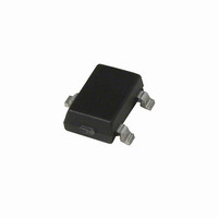
A1213LLHLT-T Allegro Microsystems Inc, A1213LLHLT-T Datasheet - Page 4

A1213LLHLT-T
Manufacturer Part Number
A1213LLHLT-T
Description
IC LATCH HALL EFFECT SOT23W
Manufacturer
Allegro Microsystems Inc
Type
Bipolar Latchr
Datasheet
1.A1214LUA-T.pdf
(13 pages)
Specifications of A1213LLHLT-T
Sensing Range
200G Trip, -200G Release
Voltage - Supply
3.8 V ~ 24 V
Current - Supply
7.5mA
Current - Output (max)
25mA
Output Type
Digital, Open Drain
Operating Temperature
-40°C ~ 150°C
Package / Case
SOT-23W
Operate Point Typ
200G
Termination Type
SMD
No. Of Pins
3
Hall Effect Type
Latching
Supply Voltage Min
3.8V
Operating Temperature Max
150°C
Peak Reflow Compatible (260 C)
Yes
Supply Voltage
24V
Filter Terminals
SMD
Rohs Compliant
Yes
Leaded Process Compatible
Yes
Operating Temperature Min
-40°C
Output Current
20mA
Lead Free Status / RoHS Status
Lead free / RoHS Compliant
Features
-
Lead Free Status / RoHS Status
Lead free / RoHS Compliant, Lead free / RoHS Compliant
A1210, A1211,
A1212, A1213,
and
OPERATING CHARACTERISTICS over full operating voltage and ambient temperature ranges, unless otherwise noted
Electrical Characteristics
Supply Voltage
Output Leakage Current
Output On Voltage
Power-On Time
Output Rise Time
Output Fall Time
Supply Current
Reverse Battery Current
Supply Zener Clamp Voltage
Supply Zener Current
Magnetic Characteristics
1
2
3
4
5
This so-called algebraic convention supports arithmetic comparison of north and south polarity values, where the relative strength of the field is indicated
by the absolute value of B, and the sign indicates the polarity of the field (for example, a –100 G field and a 100 G field have equivalent strength, but
opposite polarity).
Operate Point
Release Point
Hysteresis
Maximum voltage must be adjusted for power dissipation and junction temperature, see Power Derating section.
For V
C
Maximum current limit is equal to the maximum I
Magnetic flux density, B, is indicated as a negative value for north-polarity magnetic fields, and as a positive value for south-polarity magnetic fields.
S
=oscilloscope probe capacitance.
A1214
CC
Characteristic
slew rates greater than 250 V/μs, and T
1
2
3
3
4
5
V
Symbol
I
I
OUTOFF
OUT(SAT)
I
EMC (Electromagnetic Compatibility) REQUIREMENTS
CCOFF
B
CCON
I
V
B
B
t
RCC
V
PO
HYS
I
CC
t
t
OP
RP
Z
r
f
Z
A
CC(max)
= 150°C, the Power-On Time can reach its maximum value.
DEVICE QUALIFICATION PROGRAM
Operating, T
V
I
Slew rate (dV
B < B
V
V
B > B
B < B
V
I
V
OUT
CC
OUT
CC
CC
RCC
Z
A1210
A1211
A1212
A1213
A1214
A1210
A1211
A1212
A1213
A1214
A1210
A1211
A1212
A1213
A1214
= 32 V; T
Contact Allegro for information.
Contact Allegro for information.
= 10.5 mA; T
+ 3 mA.
= 12 V, R
= 12 V, R
= 20 mA, B > B
= 24 V, B < B
RP
OP
RP
= –30 V
– 5 G
A
J
South pole adjacent to branded face
of device
North pole adjacent to branded face
of device
B
CC
LOAD
LOAD
= 25°C
< 165°C
OP
/dt) < 2.5 V/μs, B > B
A
Test Conditions
– B
= 25°C
RP
= 820 Ω, C
= 820 Ω, C
OP
RP
Continuous-Time Latch Family
S
S
= 12 pF
= 12 pF
OP
+ 5 G or
115 Northeast Cutoff
1.508.853.5000; www.allegromicro.com
Allegro MicroSystems, Inc.
Worcester, Massachusetts 01615-0036 U.S.A.
–150
–180
–175
–200
–300
Min.
140
100
160
280
3.8
32
25
15
50
80
50
80
–
–
–
–
–
–
–
–
–
–117
Typ.
215
107
–78
–95
155
180
225
4.1
3.8
78
87
–
–
–
–
–
–
–
–
–
–
–
–
–
–
Max.
–140
10.5
400
400
400
–10
150
180
175
200
300
–25
–15
–50
–80
350
400
600
7.5
7.5
24
10
4
–
–
–
Units
mV
mA
mA
mA
mA
μA
μs
ns
ns
V
V
G
G
G
G
G
G
G
G
G
G
G
G
G
G
G
4


