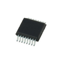
AS5035-T austriamicrosystems, AS5035-T Datasheet - Page 3

AS5035-T
Manufacturer Part Number
AS5035-T
Description
IC ENCODER ROTARY 8-BIT 16-SSOP
Manufacturer
austriamicrosystems
Type
Linear, Rotary Encoder - Programmabler
Datasheet
1.AS5035-T.pdf
(17 pages)
Specifications of AS5035-T
Sensing Range
45mT ~ 75mT
Voltage - Supply
3 V ~ 3.6 V, 4.5 V ~ 5.5 V
Current - Supply
25mA
Current - Output (max)
4mA
Output Type
Quadrature with Index (Incremental)
Features
Programmable
Operating Temperature
-40°C ~ 125°C
Package / Case
16-SSOP
Lead Free Status / RoHS Status
Lead free / RoHS Compliant
Other names
AS5035-TTR
AS5035 – 64 PPR INCREMENTAL MAGNETIC ROTARY ENCODER
5
5.1
5.1.1
Connect a 4.5V to 5.5V power supply to pin VDD5V only.
Add a 1µF to 10µF buffer capacitor to pin VDD3V3
5.1.2
Connect a 3.0V to 3.6 V power supply to both pins VDD5V
and VDD3V3. If necessary, add a 100nF ceramic buffer
capacitor to pin VDD3V3.
Revision 1.5
Figure 4: Connections for 5V / 3.3V supply voltages
Connecting the AS5035
Power Supply
4.5 - 5.5V
3.0 - 3.6V
5V Operation
3.3V Operation
5.0V Operation
3.3V Operation
100n
VDD5V
VDD5V
VSS
VSS
LDO
LDO
VDD3V3
VDD3V3
2.2...10µF
Internal
VDD
N
R
C
Internal
VDD
N
R
C
T
E
F
A
E
T
E
F
A
E
I
I
Prog
OTP_CLK
OTP_DO
A
B
Index
CSn
A
B
Index
CSn
Prog
OTP_CLK
OTP_DO
100n
www.austriamicrosystems.com
5.2
VDD5V will be either 3.0 - 3.6V or 4.5 - 5.5V, depending on
configuration.
In either case, the logic levels on output pins A, B and
Index will be
Vout high = VDD5V – 0.5V,
Vout low = VSS+0.4V.
The logic level on the CSn input pin will be
Vin high = VDD5V*0.7,
Vin low = VDD5V*0.3
5.3
The available maximum output current on pins A, B and
Index to maintain the Vout high and Vout low levels is
2mA (sink and source) at VDD5V = 3.0V
4mA (sink and source) at VDD5V = 4.5V
5.4
5.4.1
For standalone operation without microcontroller, pin CSn
should be connected to VSS permanently. The incremental
outputs will be available, as soon as the internal offset
compensation is finished (within <50ms).
5.4.2
A diagnostic feature is available to detect a temporary loss
of
if the CSn pin is high or left open (internal pull up resistor
~50kΩ) during power-up, the incremental outputs will
remain in high state: A = B = Index = High.
This state indicates a power-up or temporary loss of power,
as in normal operation A, B and Index will never be high at
the same time. When Index is high, both A and B are low.
To clear this state end enable the incremental outputs,
CSn must be pulled low. The incremental outputs will
remain enabled if CSn returns to high afterwards.
power
Logic High and Low Levels
Output Current
Chip Select Pin CSn
Without Power-up Diagnostic Feature
With Power-up Diagnostic Feature
or
initial
power-up
of
the
Page 3 of 17
AS5035:


