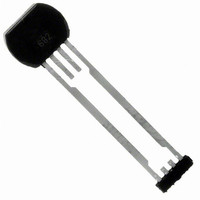
ATS682LSHTN-T Allegro Microsystems Inc, ATS682LSHTN-T Datasheet - Page 13

ATS682LSHTN-T
Manufacturer Part Number
ATS682LSHTN-T
Description
IC HALL EFFECT SENSOR 4SIP
Manufacturer
Allegro Microsystems Inc
Type
Linear Field Sensorr
Datasheet
1.ATS682LSHTN-T.pdf
(16 pages)
Specifications of ATS682LSHTN-T
Package / Case
4-SIP
Sensing Range
120mV Trip, 120mV Release
Voltage - Supply
4 V ~ 24 V
Current - Supply
16.8mA
Output Type
Analog
Features
Gear Tooth Type
Operating Temperature
-40°C ~ 150°C
Bandwidth
40kHz
Supply Voltage Max
24V
Hall Effect Type
Gear Tooth
Operating Temperature Range
-40°C To +150°C
Supply Voltage Min
4V
Lead Free Status / RoHS Status
Lead free / RoHS Compliant
Current - Output (max)
-
Lead Free Status / RoHS Status
Lead free / RoHS Compliant, Lead free / RoHS Compliant
Other names
620-1327-2
Available stocks
Company
Part Number
Manufacturer
Quantity
Price
Company:
Part Number:
ATS682LSHTN-T
Manufacturer:
ST
Quantity:
101
ATS682LSH
Characteristic Allowable Signal Amplitude Variation
The colored area in figure 10 shows B
area of allowable magnetic signal amplitude within which the IC
will continue output switching. The output duty cycle is wholly
dependent on the magnetic signature of the target across the air
gap range of movement, and may not always be within specifi-
cation throughout the entire operating region (to B
Signal amplitude changes may be due to deflection (relative air
Figure 10. Allowable Signal Amplitude Change chart
Figure 11. Illustration of B
variation discussion. B
calibration cycle B
magnetic amplitudes during IC operation.
B
SOA
CAL
0.2
0.3
0.4
0.5
0.6
0.7
0.8
0.9
1.0
1.1
, the safe operating
1
2
DIFF
DIFF
(max) and B
CAL
(max)).
x
3
Miniature, Two-Wire, True Zero Speed
CAL
Differential Peak-Detecting Sensor IC
is the magnetic amplitude at the IC during its
, B
B
B
4
DIFF
DIFF
DIFF
DIFF(lim)
(max) and B
(max) / B
Safe Operating
(max)
5
gap change between Hall element and target), target eccentricity,
magnet temperature coefficient or a combination thereof.
The axis parameters for the chart in figure 10 are defined in fig-
ure 11. As an example, assume the case where the signal changes
from the nominal at the installed air gap (B
defined by an increase factor of B
decrease of B
“x” in figure 10.
Area
are the maximum and minimum
CAL
6
DIFF(lim)
7
Guard-banded
Nominal
DIFF(lim)
for amplitude
8
B
DIFF(lim)
/ B
9
CAL
115 Northeast Cutoff
1.508.853.5000; www.allegromicro.com
Allegro MicroSystems, Inc.
Worcester, Massachusetts 01615-0036 U.S.A.
= 0.75. This case is plotted with an
DIFF
(max) / B
CAL
) within the range
CAL
= 3.0, and a
13


