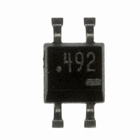
DN6849S Panasonic - SSG, DN6849S Datasheet - Page 5

DN6849S
Manufacturer Part Number
DN6849S
Description
IC HALL EFF SENSOR BI-DIR SOH-4D
Manufacturer
Panasonic - SSG
Type
Bipolar Latchr
Datasheets
1.DN6849S.pdf
(7 pages)
2.DN6849S.pdf
(3 pages)
3.DN6849S.pdf
(3 pages)
4.DN6849S.pdf
(7 pages)
Specifications of DN6849S
Sensing Range
-17.5mT Trip, 17.5mT Release
Voltage - Supply
4.5 V ~ 16 V
Current - Supply
6mA
Current - Output (max)
10µA
Output Type
Digital, Open Collector
Features
High Sensitivity
Operating Temperature
-40°C ~ 100°C
Package / Case
SOH-4D
Lead Free Status / RoHS Status
Contains lead / RoHS non-compliant
■ Caution on Use of Hall ICs (continued)
7. Fixing a Hall IC
8. On fixing a Hall IC to holder
9. On using flux in soldering
10. In case of the magnetic field of a magnet is too strong
11. On mounting , deburring and soldering of insertion type package
12. On surface treatment of mini-mold package
13. On soldering of the surface mount type package
vibration, fix it firmly with a holder. Otherwise, vibration may cause metal fatigue in the lead wire of Hall IC,
resulting in wire breakage.
is large, the lead wire of the Hall IC will be stretched and it may give a stress to the Hall IC.
and the lead wire may be weakened and cause a minute gap resulting in the deterioration of its resistance to moisture.
ingredients of halogen group may enter where the lead frame and package resin joint, causing corrosion and the
disconnection of the aluminum wiring on the surface of an IC chip.
density should be used within the range of 100 mT.
circuit board, abnormal stress is applied to the package and the reliability of the Hall IC is likely to deteriorate. So,
when mounting each Hall IC of the insertion type, insert the leads in due degree at which the bottom face of the
package is separated at least 2 mm from the top face of the PCB.
much as possible in the deburring process, but in some cases, they are not perfectly removable.)
mounting. Therefore, avoid the mounting by flow (dipping) and a soldering iron. Please mount it by reflow soldering
abiding by its recommended conditions.
When a Hall IC is mounted on the printed circuit board with a holder and the coefficient of expansion of the holder
If the lead wire is stressed intensely due to the distortion of holder or board, the adhesives between the package
Sensitivity may also be changed by this stress.
Choose a flux which does not include ingredients from halogen group, such as chlorine, fluorine, etc. The
If the leads of a Hall IC in an insertion type package are inserted up to their root part through holes on the printed
Also note that burrs of epoxy resin may be left sticking to the lead wires. (We are trying to remove such burrs as
Surface treatment is available in either smooth or dull finish.
Surface mounting type Hall ICs are apt to change its electrical characteristics due to the stress from soldering at
When the Hall IC of an insertion type package installed by soldering the lead wire only is to be used under
Output may be inverted when applying a magnetic flux density of 100 mT or more. Accordingly, magnetic flux
Remaining burrs
Printed board
2 mm
SPC00004CEB
When soldering the leads, remenber to separate
the soldering position by 2 mm or more from
the resin part of the package.
DN6849/SE/S
5


