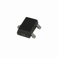
A1381LLHLT-T Allegro Microsystems Inc, A1381LLHLT-T Datasheet - Page 15

A1381LLHLT-T
Manufacturer Part Number
A1381LLHLT-T
Description
IC SENSOR HALL EFFECT SOT23-W
Manufacturer
Allegro Microsystems Inc
Type
Linear - Programmabler
Datasheet
1.A1381ELHLT-T.pdf
(19 pages)
Specifications of A1381LLHLT-T
Sensing Range
6mV/G ~ 9mV/G
Voltage - Supply
4.5 V ~ 5.5 V
Current - Supply
8mA
Current - Output (max)
10mA
Output Type
Analog, Ratiometric
Operating Temperature
-40°C ~ 150°C
Package / Case
SOT-23W
Peak Reflow Compatible (260 C)
Yes
Accuracy %
1.5%
Supply Voltage
5V
Output Current
2mA
Termination Type
SMD
Bandwidth
12kHz
Supply Voltage Max
5.5V
Sensitivity
6 To 9 MV/G
Leaded Process Compatible
Yes
No. Of Pins
3
Hall Effect Type
Linear
Supply Voltage Min
4.5V
Operating Temperature Max
150°C
Rohs Compliant
Yes
Filter Terminals
SMD
Operating Temperature Min
-40°C
Lead Free Status / RoHS Status
Lead free / RoHS Compliant
Features
-
Lead Free Status / RoHS Status
Lead free / RoHS Compliant, Lead free / RoHS Compliant
Other names
620-1196-2
A1381, A1382,
A1383, and A1384
Initial State
reset to a known state. This is referred to as the Initial state. All
the bit field locations that have intact fuses are set to logic 0.
While in the Initial state, any V
ignored. To enter the Parameter Selection state, apply one V
pulse on the VOUT pin.
Parameter Selection State
parameter register containing the bit fields to be programmed. To
select a parameter register, increment through the keys by apply-
ing V
following programming parameters:
•
•
•
To enter the Bit Field Addressing state, apply one V
the VOUT pin.
1 pulse - Sens
2 pulses - V
3 pulses - TC
PM
pulses on the VOUT pin. Register keys select among the
After system power-up, the programming logic is
OUT(Q)
V
V
PM
PH
SENS
= V
= V
, POL, and LOCK
P(LOW)
P(LOW)
–V
–V
This state allows the selection of the
P(HIGH)
P(MID)
PM
–V
pulses on the VOUT pin are
–V
Programmable Linear Hall Effect Sensor ICs with Analog Output
V
V
P(LOW)
PM
PM
P(LOW)
Available in a Miniature Thin Profile Surface Mount Package
SENS
1
Programming State Machine
V
V
PM
PM
PH
pulse on
Bit Field Addressing
User Power-Down
Parameter Selection
PH
Fuse Blowing
V
Power-Up
Required
PH
V
Initial
OUT(Q)
2
V
V
PH
PH
Bit Field Addressing State
individual bit fields to be programmed in the selected parameter
register (see Programming Logic table). To leave this state, either
cycle device power or blow the fuses for the selected code. Note
that merely addressing the bit field does not permanently set
the value of the selected programming parameter; fuses must be
blown to do so.
Fuse Blowing State
V
cycled before additional programming is attempted. Note: Each
bit representing a decimal code must be blown individually (see
the Fuse Blowing section).
PH
V
V
PM
PM
pulse on the VOUT pin. Power to the device should then be
V
PM
V
TC
2
n = total
register
PH
LOCK
POL,
bits in
n
SENS
– 1
To blow an addressed bit field, apply a
,
V
V
PM
PM
115 Northeast Cutoff, Box 15036
Allegro MicroSystems, Inc.
Worcester, Massachusetts 01615-0036 (508) 853-5000
www.allegromicro.com
This state allows the selection of the
15


