M1CVR 230V BROYCE CONTROL, M1CVR 230V Datasheet
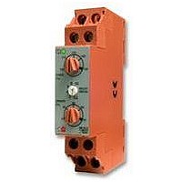
M1CVR 230V
Manufacturer Part Number
M1CVR 230V
Description
RELAY, SINGLE PHASE
Manufacturer
BROYCE CONTROL
Datasheet
1.M1CVR_230V.pdf
(1 pages)
Specifications of M1CVR 230V
Contact Configuration
SPDT
Power Consumption
13VA
Supply Voltage Max
230VAC
Relay Mounting
DIN Rail
Control Voltage Type
AC
Ac Power
4VA
Contact Current Ac Max
8A
Contact Current Dc Max
8A
Adjustment Type
Knob
Applying power.
Setting the unit.
Troubleshooting.
The table below shows the status of the unit during a fault condition.
Type: M1CVR
Single Phase, Under and Over Voltage plus Time Delay
q
q
q
q
q
q
q
q
q
Supply fault
Supply missing
Under or Over Voltage condition (during timing)
Under or Over Voltage condition (after timing)
Supply below 70% of Un (fixed under trip level [2])
Supply below 50% of Un
Telephone: +44 (0) 1902 773746 Facsimile: +44 (0) 1902 420639 Email: sales@broycecontrol.com Web: http://www.broycecontrol.com
The information provided in this literature is believed to be accurate (subject to change without prior notice); however, use of such information shall be entirely at the user’s own risk.
FUNCTION DIAGRAM
INSTALLATION AND SETTING
BEFORE INSTALLATION, ISOLATE THE SUPPLY.
Connect the unit as required. The diagram below shows a typical installation, whereby the supply to
the load is being monitored by the relay. If a fault should occur (i.e. fuse blowing), the contactor or
relay is de-energised removing the supply to the load. The contactor or relay only re-energises after
the fault has cleared.
Set the “over %” adjustment to maximum and the “under %” adjustment to minimum. Set the
“time delay” to minimum.
Apply power and the green “supply on” and red “relay” LED’s will illuminate, the relay will energise
and contacts 15 and 18 will close. Refer to the troubleshooting table if the unit fails to operate
correctly.
Set the “over %” and the “under %” adjustments to give the required monitoring range.
If large supply variations are anticipated, the adjustments should be set further from the nominal
voltage.
Set the “time delay” as required. (Note that the delay is only effective should the supply increase
above or drop below the set trip levels. However, if during an under voltage condition the supply
drops below the 2
de-energises).
CONNECTION DIAGRAM
17.5mm DIN rail housing
Microproccessor controlled with internal monitoring (self-checking)
Monitors own supply
Detects if supply exceeds the set Under or Over Voltage trip levels
Fixed trip level - 70% of Un (time delay automatically cancelled when the supply drops below
this level)
Adjustments for under and over voltage trip level
Adjustment for time delay (from under or over voltage condition)
1 x SPDT relay output 8A
Intelligent LED indication for supply and relay status
Monitored
Fixed
Under trip
L
N
Supply
Supply / Monitored
Local Fuse
Voltage
Board
nd
under voltage trip level, any set time delay is automatically cancelled and the relay
Over trip
Hyst.
Hyst.
Under trip
Td
t
Broyce Control Ltd., Pool Street, Wolverhampton, West Midlands WV2 4HN. England
Voltage monitor
t
Green LED
Off
On
On
On
Off
A1
16 18
15
A2
t
Red LED
Off
Flashing
Off
Off
Off
Contactor or
Installation work must be carried
Relay
out by qualified personnel.
To Load
tr
Relay
De-energised
Energised for set delay (t)
De-energised
De-energised
De-energised
Td
Supply / monitoring
Frequency range:
Supply variation:
Isolation:
Rated impulse
Power consumption:
(max.)
Trip levels:
Measuring ranges:
Repeat accuracy:
Hysteresis:
Response time:
Time delay (t):
Delay from
Power on delay (Td):
Ambient temp:
Relative humidity:
Output:
Output rating:
Electrical life:
Dielectric voltage:
Rated impluse
Housing:
Weight:
Mounting option:
Terminal conductor size:
Approvals:
Options:
1.
2.
voltage Un*:
withstand voltage:
withstand voltage:
supply loss (tr):
TECHNICAL SPECIFICATION
For other supply/monitoring voltages*, please contact Sales.
The unit is also available with a double-pole relay output. Refer to separate data sheet
for M3cvr/2.
MOUNTING DETAILS
surface mounting
Withdraw clips
fully when
Insert screwdriver
Under [2]:
Over:
Under:
24V:
110V:
115V:
220V:
230V:
240V:
to release clips
to DIN 43880
24, 110, 115, 220, 230, 240V AC
48 - 63Hz
70 - 130% of Un
Over voltage cat. III
4kV (1.2 / 50 S) IEC 60664
70% of Un (fixed)
75 - 95% of Un
105 - 125% of Un
Under
18 - 23V
82 - 104V
86 - 109V
165 - 209V
173 - 218V
180 - 228V
0.2 - 10 sec ( 5%)
Note: actual delay (t) = adjustable delay + response time
-20 to +60 C
+95%
SPDT relay
AC1
AC15
DC1
2kV AC (rms) IEC 60947-1
4kV (1.2 / 50 S) IEC 60664
Orange flame retardant UL94 VO
On to 35mm symmetric DIN rail to BS5584:1978
(EN50 002, DIN 46277-3) Or direct surface mounting via 2 x
M3.5 or 4BA screws using the black clips provided on the rear
of the unit.
Conforms to IEC. CE and
1.4VA (24V)
6.2VA (110/115V)
13VA (220/230/240V)
0.5% @ constant conditions
2% of trip level (factory set)
50 mS
100 mS (worst case = tr x 2)
1sec. (worst case = Td x 2)
150,000 ops at rated load
70g
2 x 2.5mm
W. 17.5mm
Dims:
89 (excl. clips)
93 (+/- 1mm)
2
solid or stranded
250V 8A (2000VA)
250V 5A (no), 3A (nc)
25V 8A (200W)
45
Compliant.
Over
25 - 30V
115 - 137V
121 - 144V
231 - 275V
241 - 287V
252 - 300V
Terminal Protection to IP20
49 59
M1CVR-2-A
Related parts for M1CVR 230V
Image
Part Number
Description
Manufacturer
Datasheet
Request
R

Part Number:
Description:
RELAY, CONDUCTIVE LEVEL CONTROL
Manufacturer:
BROYCE CONTROL
Datasheet:
Part Number:
Description:
RELAY, CONDUCTIVE LEVEL CONTROL, 230VAC
Manufacturer:
BROYCE CONTROL
Datasheet:

Part Number:
Description:
RELAY, THERMISTOR
Manufacturer:
BROYCE CONTROL
Datasheet:

Part Number:
Description:
TEMPERATURE CONTROLLER, PT100
Manufacturer:
BROYCE CONTROL
Datasheet:

Part Number:
Description:
RELAY, UNDER/OVER CURRENT
Manufacturer:
BROYCE CONTROL
Datasheet:

Part Number:
Description:
RELAY, MULTIFUNCTION, CURRENT
Manufacturer:
BROYCE CONTROL
Datasheet:
Part Number:
Description:
RELAY, 3PHASE ASYMMETRY, 400VAC
Manufacturer:
BROYCE CONTROL
Datasheet:
Part Number:
Description:
RELAY,EARTH LEAKAGE VARIABLE
Manufacturer:
BROYCE CONTROL
Datasheet:
Part Number:
Description:
RELAY,EARTH LEAKAGE VARIABLE PANEL
Manufacturer:
BROYCE CONTROL
Datasheet:

Part Number:
Description:
RELAY, SEQUENCE/LOSS
Manufacturer:
BROYCE CONTROL
Datasheet:

Part Number:
Description:
RELAY, PHASE SEQUENCE FAILURE
Manufacturer:
BROYCE CONTROL
Datasheet:
Part Number:
Description:
RELAY,SEQUENCE/LOSS, 3PHASE
Manufacturer:
BROYCE CONTROL
Datasheet:

Part Number:
Description:
INDICATOR, 3 PHASE
Manufacturer:
BROYCE CONTROL
Datasheet:

Part Number:
Description:
RELAY, SEQUENCE/LOSS, 3PHASE
Manufacturer:
BROYCE CONTROL
Datasheet:

Part Number:
Description:
RELAY, SEQUENCE/LOSS, 3PHASE
Manufacturer:
BROYCE CONTROL
Datasheet: