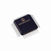
PIC16C74B-04/PQ Microchip Technology, PIC16C74B-04/PQ Datasheet - Page 7

PIC16C74B-04/PQ
Manufacturer Part Number
PIC16C74B-04/PQ
Description
IC,MICROCONTROLLER,8-BIT,PIC CPU,CMOS,QFP,44PIN,PLASTIC
Manufacturer
Microchip Technology
Series
PIC® 16Cr
Datasheets
1.PIC16F616T-ISL.pdf
(8 pages)
2.PIC16F818-ISO.pdf
(6 pages)
3.PIC16C63A-04SP.pdf
(184 pages)
4.PIC16C63A-04SP.pdf
(10 pages)
5.PIC16C63A-04SP.pdf
(10 pages)
Specifications of PIC16C74B-04/PQ
Rohs Compliant
YES
Core Processor
PIC
Core Size
8-Bit
Speed
4MHz
Connectivity
I²C, SPI, UART/USART
Peripherals
Brown-out Detect/Reset, POR, PWM, WDT
Number Of I /o
33
Program Memory Size
7KB (4K x 14)
Program Memory Type
OTP
Ram Size
192 x 8
Voltage - Supply (vcc/vdd)
4 V ~ 5.5 V
Data Converters
A/D 8x8b
Oscillator Type
External
Operating Temperature
0°C ~ 70°C
Package / Case
44-MQFP, 44-PQFP
Processor Series
PIC16C
Core
PIC
Data Bus Width
8 bit
Data Ram Size
192 B
Interface Type
I2C, SPI, USART
Maximum Clock Frequency
4 MHz
Number Of Programmable I/os
33
Number Of Timers
8
Operating Supply Voltage
2.5 V to 5.5 V
Maximum Operating Temperature
+ 70 C
Mounting Style
SMD/SMT
3rd Party Development Tools
52715-96, 52716-328, 52717-734
Development Tools By Supplier
ICE2000, DM163022
Minimum Operating Temperature
0 C
On-chip Adc
8 bit
Lead Free Status / RoHS Status
Lead free / RoHS Compliant
Eeprom Size
-
Lead Free Status / Rohs Status
Details
Available stocks
Company
Part Number
Manufacturer
Quantity
Price
Company:
Part Number:
PIC16C74B-04/PQ
Manufacturer:
Microchip Technology
Quantity:
10 000
3. Module: RESET
2003 Microchip Technology Inc.
Section 13.4.1 (“POWER-ON RESET (POR)”) has
been amended to clarify the minimum specifica-
tions required for MCLR in order to reset the
PIC16CXXX. The following paragraphs and figure
have been added:
If a MCLR pulse occurs that is less that the mini-
mum specification (parameter #30), improper
device operation can occur.
If the minimum specification cannot be met, then
an external circuit must be used to ensure that any
pulse width less than the specification will be
filtered before it reaches the MCLR pin.
A possible circuit to remedy this is shown in
Figure 6. This circuit works by delaying the MCLR
release following a power-up. If no delay is
required, the capacitor may be omitted.
An alternative would be to use a supervisory circuit
to control MCLR.
Design validation should be performed to verify
that the application works as expected.
PIC16C63A/65B/73B/74B
FIGURE 6:
V
DD
4.7 kΩ
0.01 µF ≤ C1 ≤ 0.1 µF
R1
C1
(optional)
≤ R1 ≤ 100 kΩ
MCLR EXTERNAL CIRCUIT
MCLR
PIC16CXXX
DS80048C-page 7


