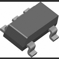
LM20BIM7 National Semiconductor, LM20BIM7 Datasheet - Page 5

LM20BIM7
Manufacturer Part Number
LM20BIM7
Description
IC, TEMPERATURE SENSOR, ± 1.5°C, SC-70-5
Manufacturer
National Semiconductor
Datasheet
1.LM20C-EVAL.pdf
(10 pages)
Specifications of LM20BIM7
Ic Output Type
Voltage
Sensing Accuracy Range
± 1.5°C
Supply Current
4.5µA
Supply Voltage Range
2.4V To 5.5V
Sensor Case Style
SC-70
No. Of Pins
5
Termination Type
SMD
Filter Terminals
SMD
Rohs Compliant
No
Lead Free Status / RoHS Status
Contains lead / RoHS non-compliant
Available stocks
Company
Part Number
Manufacturer
Quantity
Price
Part Number:
LM20BIM7
Manufacturer:
NS/国半
Quantity:
20 000
Company:
Part Number:
LM20BIM7-NOPB
Manufacturer:
NSC
Quantity:
218
Part Number:
LM20BIM7/NOPB
Manufacturer:
NS
Quantity:
20 000
Company:
Part Number:
LM20BIM7NOPB
Manufacturer:
TOSHIBA
Quantity:
6 186
Company:
Part Number:
LM20BIM7X
Manufacturer:
NSC
Quantity:
20 000
Company:
Part Number:
LM20BIM7X
Manufacturer:
NS
Quantity:
8 100
Part Number:
LM20BIM7X
Manufacturer:
NS/国半
Quantity:
20 000
Company:
Part Number:
LM20BIM7X/LM20/LM20BI/LM20B
Manufacturer:
YICHENG
Quantity:
100
Part Number:
LM20BIM7X/NOPB
Manufacturer:
TI/德州仪器
Quantity:
20 000
PCB Layouts Used for Thermal Measurements
1.0 LM20 Transfer Function
The LM20's transfer function can be described in different
ways with varying levels of precision. A simple linear transfer
function, with good accuracy near 25°C, is
Over the full operating temperature range of −55°C to +130°
C, best accuracy can be obtained by using the parabolic
transfer function.
solving for T:
A linear transfer function can be used over a limited temper-
ature range by calculating a slope and offset that give best
results over that range. A linear transfer function can be cal-
culated from the parabolic transfer function of the LM20. The
slope of the linear transfer function can be calculated using
the following equation:
T
min
Temperature Range
−55
−40
−30
−10
+35
+20
-40
V
(°C)
a) Layout used for no heat sink measurements.
O
= (−3.88×10
V
O
= −11.69 mV/°C × T + 1.8663 V
T
max
+130
+110
+100
+85
+65
+45
+30
−6
(°C)
×T
FIGURE 2. First order equations optimized for different temperature ranges.
2
) + (−1.15×10
FIGURE 1. PCB Lyouts used for thermal measurements.
10090829
−11.79 mV/°C × T + 1.8528 V
−11.77 mV/°C × T + 1.8577 V
−11.77 mV/°C × T + 1.8605 V
−11.67 mV/°C × T + 1.8583 V
−11.71 mV/°C × T + 1.8641 V
−11.81 mV/°C × T + 1.8701 V
−11.69 mV/°C × T + 1.8663 V
−2
×T) + 1.8639
Linear Equation
V
O
=
5
b) Layout used for measurements with small heat hink.
where T is the middle of the temperature range of interest and
m is in V/°C. For example for the temperature range of T
= −30 to T
and
The offset of the linear transfer function can be calculated us-
ing the following equation:
where:
•
•
Using this procedure the best fit linear transfer function for
many popular temperature ranges was calculated in
2. As shown in
linear transfer function increases with wider temperature
ranges.
V
the parabolic transfer function for V
V
parabolic transfer function for V
OP
OP
(T
(T) is the calculated output voltage at T using the
b = (V
MAX
MAX
) is the calculated output voltage at T
Maximum Deviation of Linear Equation from
= +100°C:
OP
m = −7.76 × 10
Figure 2
(T
MAX
m = −11.77 mV/°C
) + V
Parabolic Equation (°C)
T = 35°C
the error that is introduced by the
OP
(T) − m × (T
−6
× T − 0.0115,
10090830
±0.004
±0.004
O
±1.41
±0.93
±0.70
±0.65
±0.23
.
O
MAX
+T))/2
www.national.com
MAX
using
Figure
MIN


