ADSP-21062CS-160 Analog Devices Inc, ADSP-21062CS-160 Datasheet - Page 26
ADSP-21062CS-160
Manufacturer Part Number
ADSP-21062CS-160
Description
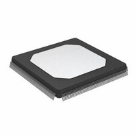
IC, FLOAT-PT DSP, 40BIT, 40MHZ, MQFP-240
Manufacturer
Analog Devices Inc
Series
SHARCr
Type
Floating Pointr
Datasheet
1.ADSP-21062KSZ-133.pdf
(64 pages)
Specifications of ADSP-21062CS-160
Frequency
40MHz
Supply Voltage
5V
Embedded Interface Type
HPI, Serial
No. Of Mips
40
Supply Voltage Range
4.75V To 5.25V
Operating Temperature Range
-40°C To +100°C
Rohs Status
RoHS non-compliant
Interface
Host Interface, Link Port, Serial Port
Clock Rate
40MHz
Non-volatile Memory
External
On-chip Ram
256kB
Voltage - I/o
5.00V
Voltage - Core
5.00V
Operating Temperature
-40°C ~ 100°C
Mounting Type
Surface Mount
Package / Case
240-MQFP, 240-PQFP
Lead Free Status / RoHS Status
Contains lead / RoHS non-compliant
Available stocks
Company
Part Number
Manufacturer
Quantity
Price
Company:

Part Number:
ADSP-21062CS-160
Manufacturer:
Analog Devices Inc
Quantity:
10 000


ADSP-21060/ADSP-21060L/ADSP-21062/ADSP-21062L/ADSP-21060C/ADSP-21060LC
Memory Write—Bus Master
Use these specifications for asynchronous interfacing to memo-
ries (and memory-mapped peripherals) without reference to
CLKIN. These specifications apply when the ADSP-2106x is the
Table 15. Memory Write—Bus Master
1
2
3
Parameter
Timing Requirements
t
t
Switching Characteristics
t
t
t
t
t
t
t
t
t
t
W = (number of wait states specified in WAIT register) × t
H = t
HI = t
I = t
ACK delay/setup: user must meet t
The falling edge of MSx, SW, BMS is referenced.
See
DAAK
DSAK
DAWH
DAWL
WW
DDWH
DWHA
DATRWH
WWR
DDWR
WDE
SADADC
(High).
Example System Hold Time Calculation on Page 47
CK
CK
CK
(if a bus idle cycle occurs, as specified in WAIT register; otherwise I = 0).
(if an address hold cycle occurs, as specified in WAIT register; otherwise H = 0).
(if an address hold cycle or bus idle cycle occurs, as specified in WAIT register; otherwise HI = 0).
RD, DMAG
ADDRESS
MSx, SW
ADRCLK
BMS
(OUT)
DATA
ACK
WR
ACK Delay from Address, Selects
ACK Delay from WR Low
Address Selects to WR Deasserted
Address Selects to WR Low
WR Pulse Width
Data Setup Before WR High
Address Hold After WR Deasserted
Data Disable After WR Deasserted
WR High to WR, RD, DMAGx Low
Data Disable Before WR or RD Low
WR Low to Data Enabled
Address, Selects Setup Before ADRCLK High
DAAK
t
or t
SADADC
t
DAWL
DSAK
t
1
DAAK
or synchronous specification t
2
for calculation of hold times given capacitive and dc loads.
1, 2
t
DSAK
3
2
Figure 15. Memory Write—Bus Master
Rev. F | Page 26 of 64 | March 2008
t
WDE
CK
2
.
t
DAWH
SAKC
for deassertion of ACK (low), all three specifications must be met for assertion of ACK
t
WW
bus master accessing external memory space in asynchronous
access mode. Note that timing for ACK, DATA, RD, WR, and
DMAGx strobe timing parameters only applies to asynchronous
access mode.
Min
17 + 15DT/16 + W
3 + 3DT/8
12 + 9DT/16 + W
7 + DT/2 + W
0.5 + DT/16 + H
1 + DT/16 +H
8 + 7DT/16 + H
5 + 3DT/8 + I
–1 + DT/16
0 + DT/4
t
DDWH
5 V and 3.3 V
t
DATRWH
t
DWHA
Max
14 + 7DT/8 + W
8 + DT/2 + W
6 + DT/16+H
t
WWR
t
DDWR
Unit
ns
ns
ns
ns
ns
ns
ns
ns
ns
ns
ns
ns
Related parts for ADSP-21062CS-160
Image
Part Number
Description
Manufacturer
Datasheet
Request
R

Part Number:
Description:
±1.7g Dual-Axis IMEMS Accelerometer Evaluation Board
Manufacturer:
Analog Devices Inc
Datasheet:

Part Number:
Description:
Inertial Sensor Evaluation System
Manufacturer:
Analog Devices Inc
Datasheet:
Part Number:
Description:
Manufacturer:
Analog Devices Inc
Datasheet:
Part Number:
Description:
Manufacturer:
Analog Devices Inc
Datasheet:
Part Number:
Description:
Manufacturer:
Analog Devices Inc
Datasheet:
Part Number:
Description:
Manufacturer:
Analog Devices Inc
Datasheet:
Part Number:
Description:
Manufacturer:
Analog Devices Inc
Datasheet:
Part Number:
Description:
Manufacturer:
Analog Devices Inc
Datasheet:
Part Number:
Description:
Manufacturer:
Analog Devices Inc
Datasheet:
Part Number:
Description:
Manufacturer:
Analog Devices Inc
Datasheet:
Part Number:
Description:
Manufacturer:
Analog Devices Inc
Datasheet:
Part Number:
Description:
Manufacturer:
Analog Devices Inc
Datasheet:
Part Number:
Description:
Manufacturer:
Analog Devices Inc
Datasheet: