PEC11L-4125K-N0020 Bourns Inc., PEC11L-4125K-N0020 Datasheet
PEC11L-4125K-N0020
Manufacturer Part Number
PEC11L-4125K-N0020
Description
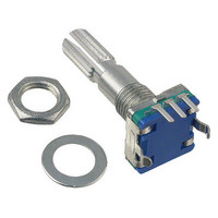
ENCODER LOW PROFILE 11MM
Manufacturer
Bourns Inc.
Series
PEC11r
Specifications of PEC11L-4125K-N0020
Termination Style
PC Pin
Encoder Type
Mechanical
Output Type
Quadrature (Incremental)
Pulses Per Revolution
20
Actuator Type
6mm Dia Knurled End
Detent
Yes
Built In Switch
No
Mounting Type
Panel, PCB Through Hole
Orientation
Vertical
Rotational Life (cycles Min)
100K
Number Of Detents
20
Mounting Style
SMD/SMT
Output
2 bit Gray Code
Shaft Type
Metal Knurled
With Switch
Without
Operating Temperature Range
- 30 C to + 70 C
Product
Mechanical
Rotational Speed Max
60rpm
Rotational Life Cycles
100000
Shaft Length
25mm
No. Of Detents
20
Rohs Compliant
Yes
Lead Free Status / RoHS Status
Lead free / RoHS Compliant
Voltage - Supply
-
Lead Free Status / Rohs Status
Lead free / RoHS Compliant


Output ..................................................................................................................................................................................................2-bit quadrature code
Closed Circuit Resistance ................................................................................................................................................................100 milliohms maximum
Contact Rating .............................................................................................................................................................................................. 10 mA @ 5 VDC
Insulation Resistance ....................................................................................................................................................................100 megohms @ 250 VDC
Dielectric Withstanding Voltage
Electrical Travel..................................................................................................................................................................................................... Continuous
Contact Bounce (60 RPM) ..........................................................................................................................................................................10 ms maximum**
RPM (Operating) .............................................................................................................................................................................................. 60 maximum**
Operating Temperature Range ......................................................................................................................................-10 °C to +70 °C (+14 °F to +158 °F)
Storage Temperature Range ......................................................................................................................................... -40 °C to +85 °C (-40 °F to +185 °F)
Humidity ............................................................................................................................................................... MIL-STD-202, Method 103B, Condition A
Vibration .......................................................................................................................................................................................................................... 30 G
Shock ............................................................................................................................................................................................................................ 100 G
Rotational Life .................................................................................................................................................................................100,000 cycles minimum
IP Rating ..........................................................................................................................................................................................................................IP 40
Mechanical Angle .........................................................................................................................................................................................360 ° continuous
Torque
Shaft Side Load (Static) ................................................................................................................................................................ 2.04 kgf (4.5 lbs) minimum
Shaft Strength (Push-Pull) ..............................................................................................................................................................................100 N (22.5 lbs)
Weight ............................................................................................................................................................................................. 5 gm (0.17 oz) maximum
Terminals ................................................................................................................................................................................ Printed circuit board terminals
Hardware ...................................................................................................................... One fl at washer and one mounting nut supplied with each encoder
Switch Type ................................................................................................................................................................... Contact Push ON Momentary SPST
Switch Life .........................................................................................................................................................................................20,000 cycles minimum
Power Rating (Resistive Load) ..................................................................................................................................................................... 10 mA at 5 V DC
Switch Travel ......................................................................................................................................................................................................0.5 ± 0.3 mm
Switch Actuation Force ...................................................................................................................................................... 610 ± 306 gf (8.47 ± 4.24 oz.-in.)
Model
Terminal Confi guration
Detent Option
Standard Shaft Length
Shaft Style
Switch Confi guration
Resolution
*RoHS Directive 2002/95/EC Jan 27, 2003 including Annex.
**Devices are tested using standard noise reduction fi lters. For optimum performance, designers should use noise reduction fi lters in their circuits.
Specifi cations are subject to change without notice.
Customers should verify actual device performance in their specifi c applications.
How To Order
Electrical Characteristics
Environmental Characteristics
Mechanical Characteristics
Switch Characteristics
Sea Level ............................................................................................................................................................................................... 300 VAC minimum
Contact Bounce............................................................................................................................................... 10~55~10 Hz / 1 min. / Amplitude 1.5 mm
Detent ...............................................................................................................................................................................20-150 gf-cm (0.27 to 2.0 oz-in)
Running ........................................................................................................................................................................ 10 to 150 gf-cm (0.14 to 2.1 oz-in)
Mounting............................................................................................................................................................................... 70 N-cm (6.2 lb-in) maximum
Soldering Condition
4 = PC Pin Horizontal/Rear Facing
0 = No Detents (15, 20 pulses)
1 = 20 Detents (20 pulses)
2 = 30 Detents (15 pulses)
15 = 15.0 mm
20 = 20.0 mm
25 = 25.0 mm
F = Metal Flatted Shaft
K = Metal Knurled Shaft
S = Push Momentary Switch
N = No Switch
0015 = 15 Pulses per 360 ° Rotation
0020 = 20 Pulses per 360 ° Rotation
Wave Soldering........................................................................... Sn95.5/Ag2.8/Cu0.7 solder with no-clean fl ux: 260 °C ±5 °C max. for 3-5 seconds
Hand Soldering .................................................................................................................................................................................Not recommended
Features
■
■
■
■
■
PEC11L Series - 11 mm Low Profi le Encoder
Push switch option
Compact, low profi le
High reliability
Metal bushing/shaft
RoHS compliant*
PEC11L - 4 0 20 F - S 0015
Related parts for PEC11L-4125K-N0020
Image
Part Number
Description
Manufacturer
Datasheet
Request
R

Part Number:
Description:
Manufacturer:
Bourns, Inc.
Datasheet:
Part Number:
Description:
11mm Potentiometer
Manufacturer:
Bourns, Inc.
Datasheet:
Part Number:
Description:
Manufacturer:
Bourns, Inc.
Datasheet:
Part Number:
Description:
Manufacturer:
Bourns, Inc.
Datasheet:
Part Number:
Description:
Manufacturer:
Bourns, Inc.
Datasheet:
Part Number:
Description:
5/16 Round Trimming Potentiometer
Manufacturer:
Bourns, Inc.
Datasheet:
Part Number:
Description:
4100R Series: Thick Film Moulded DIPs - Resistor Networks
Manufacturer:
Bourns, Inc.
Datasheet:
Part Number:
Description:
PROTECTOR - SINGLE BIDIRECTIONAL
Manufacturer:
Bourns, Inc.
PEC11L-4125K-N0020 Summary of contents
Page 1
... Specifi cations are subject to change without notice. Customers should verify actual device performance in their specifi c applications. Features ■ Push switch option ■ Compact, low profi le ■ High reliability ■ Metal bushing/shaft ■ RoHS compliant* PEC11L Series - 11 mm Low Profi le Encoder PEC11L - 0015 ...
Page 2
... Applications Level control, tuning and timer settings in: ■ Audio-visual equipment ■ Consumer electric appliances ■ Environmental controls ■ Musical instrumentation ■ Communications equipment PEC11L Series - 11 mm Low Profi le Encoder Product Dimensions PEC11L-4xxxF-Nxxxx 0.75 M7XP (.030) 2.0 (.079) 7.5 (.295 ...