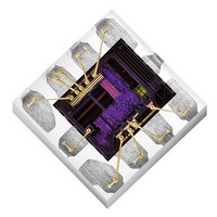
Si1143-A10-GM Silicon Laboratories Inc, Si1143-A10-GM Datasheet - Page 24

Si1143-A10-GM
Manufacturer Part Number
Si1143-A10-GM
Description
Proximity Sensors IC INTERFACE
Manufacturer
Silicon Laboratories Inc
Datasheet
1.SI1142-A10-GM.pdf
(70 pages)
Specifications of Si1143-A10-GM
Maximum Operating Temperature
+ 85 C
Supply Voltage
3.3 V
Supply Current
5.6 mA to 360 mA
Operating Supply Voltage
1.8 V to 3.6 V
Mounting Style
SMD/SMT
Minimum Operating Temperature
- 40 C
Current Rating
359 mA
Voltage Rating
4 V
Sensing Distance
1 m
Lead Free Status / RoHS Status
Lead free / RoHS Compliant
Si1141/42/43
The interrupts of the Si1141/42/43 are controlled through the INT_CFG, IRQ_ENABLE, IRQ_MODE1,
IRQ_MODE2 and IRQ_STATUS registers.
The INT hardware pin is enabled through the INT_OE bit in the INT_CFG register. The hardware essentially
performs an AND function between the IRQ_ENABLE register and IRQ_STATUS register. After this AND function,
if any bits are set, the INT pin is asserted. The INT_MODE bit in the INT_CFG register is conceptually a method of
determining how the INT pin is deasserted. When INT_MODE = 0, the host is responsible for clearing the interrupt
by writing to the INT_STATUS register. When the specific bits of the INT_STATUS register is written with '1', that
specific INT_STATUS bit is cleared.
Typically, the host software is expected to read the INT_STATUS register, stores a local copy, and then writes the
same value back to the INT_STATUS to clear the interrupt source. Unless specifically stated, INT_MODE should
be zero for normal interrupt handling operation. In summary, the INT_CFG register is normally written with '1'.
The IRQ_MODE1, IRQ_MODE2 and IRQ_ENABLE registers work together to define how the internal sequencer
sets bits in the IRQ_STATUS register (and as a consequence, asserting the INT pin).
The PS1 interrupts are described in Table 8. The PS2 interrupts are described in Table 9. The PS2 interrupts are
described in Table 10. The ALS interrupts are described in Table 11, and the Command Interface interrupts are
described in Table 12.
24
Pin Name
LED1
LED2
LED3
INT
LED1_I in PSLED12[3:0]
LED2_I in PSLED12[7:4]
LED3_I in PSLED3[3:0]
LED Current Drive
Table 9. Resource Summary for Hardware Pins
Rev. 1.1
INT_OE in INT_CFG[0]
Output Drive Disable
HW_KEY[7:0]
HW_KEY[7:0]
Analog Voltage Input
ANA_IN_KEY[31:0]
ANA_IN_KEY[31:0]
ANA_IN_KEY[31:0]
Enable


