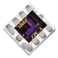
Si1142-A10-GM Silicon Laboratories Inc, Si1142-A10-GM Datasheet - Page 12

Si1142-A10-GM
Manufacturer Part Number
Si1142-A10-GM
Description
Proximity Sensors IC INTERFACE
Manufacturer
Silicon Laboratories Inc
Datasheet
1.SI1142-A10-GM.pdf
(70 pages)
Specifications of Si1142-A10-GM
Maximum Operating Temperature
+ 85 C
Supply Voltage
3.3 V
Supply Current
5.6 mA to 360 mA
Operating Supply Voltage
1.8 V to 3.6 V
Mounting Style
SMD/SMT
Minimum Operating Temperature
- 40 C
Current Rating
359 mA
Voltage Rating
4 V
Sensing Distance
1 m
Lead Free Status / RoHS Status
Lead free / RoHS Compliant
Available stocks
Company
Part Number
Manufacturer
Quantity
Price
Company:
Part Number:
Si1142-A10-GMR
Manufacturer:
SILICON
Quantity:
4 300
Part Number:
Si1142-A10-GMR
Manufacturer:
SILICON LABS/芯科
Quantity:
20 000
Si1141/42/43
When operating in the lower signal range, it is possible to saturate the ADC when the ambient light level is high.
Any overflow condition is reported in the RESPONSE register, and the corresponding data registers report a value
of 0xFFFF. The host can then adjust the ADC sensitivity. Note however that the overflow condition is not sticky. If
the light levels return to a range within the capabilities of the ADC, the corresponding data registers begin to
operate normally. However, the RESPONSE register will continue to hold the overflow condition until a NOP
command is received. Even if the RESPONSE register has an overflow condition, commands are still accepted
and processed.
Proximity detection ranges beyond 50 cm and up to several meters can be achieved without lensing by selecting a
longer integration time. The detection range may be increased further, even with high ambient light, by averaging
multiple measurements. Refer to “AN498: Designer's Guide for the Si114x” for more details.
2.3. Ambient Light
The Si1141/42/43 has photodiodes capable of measuring both visible and infrared light. However, the visible
photodiode is also influenced by infrared light. The measurement of illuminance requires the same spectral
response as the human eye. If an accurate lux measurement is desired, the extra IR response of the visible-light
photodiode must be compensated. Therefore, to allow the host to make corrections to the infrared light’s influence,
the Si1141/42/43 reports the infrared light measurement on a separate channel. The separate visible and IR
photodiodes lend themselves to a variety of algorithmic solutions. The host can then take these two measurements
and run an algorithm to derive an equivalent lux level as perceived by a human eye. Having the IR correction
algorithm running in the host allows for the most flexibility in adjusting for system-dependent variables. For
example, if the glass used in the system blocks visible light more than infrared light, the IR correction needs to be
adjusted.
If the host is not making any infrared corrections, the infrared measurement can be turned off in the CHLIST
parameter.
By default, the measurement parameters are optimized for indoor ambient light levels where it is possible to detect
light levels as low as 6 lx. For operation under direct sunlight, the ADC can be programmed to operate in a high
signal operation so that it is possible to measure direct sunlight without overflowing the 16-bit result.
For low-light applications, it is possible to increase the ADC integration time. Normally, the integration time is
25.6 µs. By increasing this integration time to 410 µs, the ADC can detect light levels as low as 1 lx. The ADC can
be programmed with an integration time as high as 3.28 ms, allowing measurement to 100 mlx light levels. The
ADC integration time for the Visible Light Ambient measurement can be programmed independently of the ADC
integration time of the Infrared Light Ambient measurement. The independent ADC parameters allow operation
under glass covers having a higher transmittance to Infrared Light than Visible Light.
When operating in the lower signal range, or when the integration time is increased, it is possible to saturate the
ADC when the ambient light suddenly increases. Any overflow condition is reported in the RESPONSE register,
and the corresponding data registers report a value of 0xFFFF. Based on either of these two overflow indicators,
the host can adjust the ADC sensitivity. However, the overflow condition is not sticky. If the light levels return to a
range within the capabilities of the ADC, the corresponding data registers begin to operate normally. The
RESPONSE register will continue to hold the overflow condition until a NOP command is received. Even if the
RESPONSE register has an overflow condition, commands are still accepted and processed.
The Si1141/42/43 can initiate ALS measurements either when explicitly commanded by the host or periodically
through an autonomous process. Refer to "3. Operational Modes" on page 16 for additional details of the Si1141/
42/43's Operational Modes. The conversion frequency setting is programmable and independent of the Proximity
Sensor. This allows the Proximity Sensor and Ambient Light sensor to operate at different conversion rates,
increasing host control over the Si1141/42/43.
When operating autonomously, the ALS has a slightly different interrupt structure compared to the Proximity
Sensor. An interrupt can be generated to the host on every sample, or when the ambient light has changed.
The “Ambient Light Changed” interrupt is accomplished through two thresholds working together to implement a
window. As long as the ambient light stays within the window defined by the two thresholds, the host is not
interrupted. When the ambient light changes and either threshold is crossed, an interrupt is sent to the host,
thereby allowing the host notification that the ambient light has changed. This can be used by the host to trigger a
recalculation of the lux values.
12
Rev. 1.1


