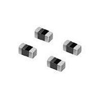
LQG15HN6N8J02D Murata, LQG15HN6N8J02D Datasheet - Page 2

LQG15HN6N8J02D
Manufacturer Part Number
LQG15HN6N8J02D
Description
RF Inductors LQG15HN6N8J02D
Manufacturer
Murata
Type
Chipr
Datasheet
1.LQG15HN6N8J02D.pdf
(2 pages)
Specifications of LQG15HN6N8J02D
Dimensions
0.5 mm W x 1 mm L x 0.5 mm H
Inductance
6.8 nH
Tolerance
5 %
Maximum Dc Current
300 mAmps
Maximum Dc Resistance
0.29 Ohms
Self Resonant Frequency
4.2 KHz
Q Minimum
8
Termination Style
SMD/SMT
Package / Case
0402 (1005 metric)
Technology
Multi-Layer
Impedance
Not RequiredOhm
Tolerance (+ Or -)
5%
Dc Resistance
290mOhm
Case Size (inches)
0402in
Operating Temp Range
-55C to 125C
Q
8
Test Frequency
100MHz
Dc Current
300mA
Product Diameter (mm)
Not Requiredmm
Product Height (mm)
0.55mm
Product Depth (mm)
0.55mm
Product Length (mm)
1mm
Military Standard
Not Required
Failure Rate
Not Required
Dc
N/A
Lead Free Status / RoHS Status
Lead free / RoHS Compliant
Available stocks
Company
Part Number
Manufacturer
Quantity
Price
Company:
Part Number:
LQG15HN6N8J02D
Manufacturer:
MURATA
Quantity:
60 000
I Q-Frequency Characteristics (Typ.)
I !Caution/Notice
! Note:
1. This datasheet is downloaded from the website of Murata Manufacturing co., ltd. Therefore, it’s specifications are subject to change or our
2. This datasheet has only typical specifications because there is no space for detailed specifications. Therefore, please approve our product
LQG15HN9N1J02p
LQG15HN10NJ02p
LQG15HN12NJ02p
LQG15HN15NJ02p
LQG15HN18NJ02p
LQG15HN22NJ02p
LQG15HN27NJ02p
LQG15HN33NJ02p
LQG15HN39NJ02p
LQG15HN47NJ02p
LQG15HN56NJ02p
LQG15HN68NJ02p
LQG15HN82NJ02p
LQG15HNR10J02p
LQG15HNR12J02p
Operating Temperature Range: -55°C to +125°C
Only for reflow soldering.
o
!Caution (Rating)
products in it may be discontinued without advance notice. Please check with our sales representatives or product engineers before ordering.
specifications or transact the approval sheet for product specifications before ordering.
Continued from the preceding page.
This data sheet is applied for CHIP INDUCTORS (CHIP COILS) used for General Electronics equipment for your design.
Do not use products beyond the rated current as
this may create excessive heat.
Part Number
100
80
60
40
20
0
100
120nH
Inductance
100nH±5%
120nH±5%
9.1nH±5%
10nH±5%
12nH±5%
15nH±5%
18nH±5%
22nH±5%
27nH±5%
33nH±5%
39nH±5%
47nH±5%
56nH±5%
68nH±5%
82nH±5%
Frequency (MHz)
1000
68nH
Test Frequency
33nH
1.5nH
100MHz
100MHz
100MHz
100MHz
100MHz
100MHz
100MHz
100MHz
100MHz
100MHz
100MHz
100MHz
100MHz
100MHz
100MHz
12nH
4.7nH
Rated Current
300mA
300mA
300mA
300mA
300mA
300mA
300mA
200mA
200mA
200mA
200mA
180mA
150mA
150mA
150mA
10000
http://www.murata.com/
Data Sheet
Max. of DC resistance Q (min.) Test Frequency
Inductors (Coils) > Chip Inductor (Chip Coil) > for High Frequency Multilayer Type
0.34ohm
0.35ohm
0.41ohm
0.46ohm
0.51ohm
0.58ohm
0.67ohm
0.67ohm
1.06ohm
1.15ohm
1.20ohm
1.25ohm
1.60ohm
1.60ohm
1.60ohm
I Inductance-Frequency Characteristics (Typ.)
Notice
Solderability of Tin plating termination chip might be
deteriorated when low temperature soldering profile
where peak solder temperature is below the Tin melting
point is used. Please confirm the solderability of Tin
plating termination chip before use.
1000
100
10
1
100
8
8
8
8
8
8
8
8
8
8
8
8
8
8
8
100MHz
100MHz
100MHz
100MHz
100MHz
100MHz
100MHz
100MHz
100MHz
100MHz
100MHz
100MHz
100MHz
100MHz
100MHz
120nH
Frequency (MHz)
1000
68nH
Self Resonance Frequency (min.)
33nH
12nH
3400MHz
3200MHz
2800MHz
2300MHz
2100MHz
1800MHz
1600MHz
1500MHz
1200MHz
1000MHz
800MHz
800MHz
600MHz
600MHz
600MHz
4.7nH
1.5nH
10000
2010.9.9
2


