B82111BC13 EPCOS Inc, B82111BC13 Datasheet - Page 3
B82111BC13
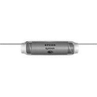
Manufacturer Part Number
B82111BC13
Description
RF Inductors 8.0uH 3.0A 0.025ohms
Manufacturer
EPCOS Inc
Series
B82111Br
Datasheet
1.B82111BC13.pdf
(7 pages)
Specifications of B82111BC13
Core Material
Ferrite
Dimensions
7 mm Dia. x 24 mm L
Inductance
8 uH
Tolerance
10 %
Maximum Dc Current
3 Amps
Maximum Dc Resistance
0.025 Ohms
Self Resonant Frequency
145 MHz
Operating Temperature Range
- 55 C to + 125 C
Termination Style
Axial
Lead Free Status / RoHS Status
Lead free / RoHS Compliant
Other names
B82111B0000C013


Technical data and measuring conditions
Test voltage V
Rated inductance L
Inductance tolerance
Rated temperature T
Rated current I
DC resistance R
Resonance frequency f
Solderability (lead-free)
Resistance to soldering heat
(wave soldering)
Tensile strength of leads
Climatic category
Storage conditions
Approvals
When bending the leads, take care that the bending point is at least 3 mm apart from the face ends
of the core and that the start-of-winding areas are not subjected to any mechanical stress.
Please read Cautions and warnings and
Important notes at the end of this document.
VHF chokes
Mounting information
test
R
typ
R
R
res
2500 V AC, 1 min
Measured with LCR meter Agilent 4284A
or impedance analyzer Agilent 4294A
Measuring frequency:
Measuring voltage:
Measuring temperature: 20 °C
±20%
60 °C
Maximum permissible DC current at rated temperature
Measured at 20 °C, tolerance ±20%, typical values
Measured with Agilent 4294A or 8753ES, 20 °C
tolerance ±30%
Sn95.5Ag3.8Cu0.7: (245 ±5) °C, (3 ±0.3) s
Wetting of soldering area ≥ 90%
(to IEC 60068-2-20, test Ta)
(260 ±5) °C, 10 s
(to IEC 60068-2-20, test Tb)
≥ 30 N (to IEC 60068-2-21, test Ua)
55/125/56 (to IEC 60068-1)
Mounted:
Packaged: –25 °C … +40 °C, ≤ 75% RH
EN 60938
–55 °C … +125 °C
3
03/08
L
10 µH < L
1 V
R
≤ 10 µH
R
≤ 1000 µH = 100 kHz
=
B82111B
1 MHz
Related parts for B82111BC13
Image
Part Number
Description
Manufacturer
Datasheet
Request
R


Part Number:
Description:
CAP .15UF 63V METAL POLY
Manufacturer:
EPCOS Inc
Datasheet:

