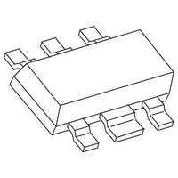
CMY210 TriQuint, CMY210 Datasheet - Page 5

CMY210
Manufacturer Part Number
CMY210
Description
RF Mixer Mixer /Receiver MMIC
Manufacturer
TriQuint
Datasheet
1.CMY210.pdf
(9 pages)
Specifications of CMY210
Frequency Range
500 MHz to 2.5 GHz
Maximum Conversation Loss
7 dB
Maximum Operating Frequency
2.5 GHz
Mounting Style
SMD/SMT
Operating Supply Voltage
3 V
Supply Current
6 mA
Package / Case
MW-6
Noise Figure
6 dB
Lead Free Status / RoHS Status
Lead free / RoHS Compliant
Other names
1014493
Available stocks
Company
Part Number
Manufacturer
Quantity
Price
Company:
Part Number:
CMY210
Manufacturer:
SIEMENS
Quantity:
5 321
Company:
Part Number:
CMY210
Manufacturer:
TriQuint
Quantity:
5 561
Company:
Part Number:
CMY210 E6327
Manufacturer:
RICHTEK
Quantity:
36 000
Part Number:
CMY210 E6327
Manufacturer:
TQ/INFINEON
Quantity:
20 000
Company:
Part Number:
CMY210 E6372
Manufacturer:
TRIQUINT
Quantity:
3 354
CMY 210 Datasheet
________________________________________________________________________________________________________
General description and notes
The CMY 210 is an all port single ended general purpose Up- and Down-Converter.
It combines small conversion losses and excellent intermodulation characteristics with a low
demand of LO- and DC-power.
The internal level controlled LO-Buffer enables a good performance over a wide LO level range.
The internal mixers principle with one port RF and IF requires a frequency separation at pin 1 and 6
respectively.
Note 1:
Best performance with lowest conversion loss is achieved when each circuit or device for the
frequency separation meets the following requirements:
Input Filter: Throughpass for the signal to be mixed; reflection of the mixed signal and the harmonics
of both.
Output Filter: Throughpass for the mixed signal and reflection of the signal to be mixed and the
harmonics of both.
The impedance for the reflecting frequency range of each filter toward the ports 1 and 6 should be as
high as possible.
In the simplest case a series- and a parallel- resonator circuit will meet these requirements but also
others as appropriate drop in filters or micro stripline elements can be used.
The two branches with filters should meet immediately at the package leads of the port 1 and 6.
Parasitic capacitances at these ports must be kept as small as possible.
The mixer also can be driven with a source- and load impedance different to 50Ω, but performance
will degrade at larger deviations.
Note 2:
The LO-Buffer needs an external inductor L4 at port 4; the value of inductance depends on the
LO frequency. It is tuned for minimum I
consumption into port 4.
op
At lower LO frequencies it can be reduced by an additional capacitor C5.
Note 3:
The LO Input impedance at Port 3 can be matched with a series inductor. It also can be tuned for a
minimum current I
into port 4. C3 is a DC blocking capacitor.
op
Since the input impedance of port 3 can be slightly negative, the source reflection coefficient should
= 50 Ω ).
be kept below 0.8 ( Z
0
The Conversion Noise Figure Fssb is corresponding with the value of Conversion Loss L
. The LO
c
± f
signal must be clean of noise and spurious at the frequencies f
.
LO
IF
6
For additional information and latest specifications, see our website:
www.triquint.com
Revision E, September 12, 2006


