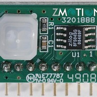
ZMOT0BSB0B0AG Zilog, ZMOT0BSB0B0AG Datasheet - Page 14

ZMOT0BSB0B0AG
Manufacturer Part Number
ZMOT0BSB0B0AG
Description
Microcontrollers (MCU) ZMB Nic RE200B-P Pyr Fr CM 0.77 GI V3 Len
Manufacturer
Zilog
Datasheet
1.ZMOT0BSB0A0BG.pdf
(66 pages)
Specifications of ZMOT0BSB0B0AG
Processor Series
ZMOTION
Core
Z8FS040
Number Of Timers
2
Operating Supply Voltage
2.7 V to 3.6 V
Maximum Operating Temperature
+ 105 C
Mounting Style
SMD/SMT
Program Memory Type
Flash
Program Memory Size
4 KB
Package / Case
SOIC-8
Lead Free Status / RoHS Status
Lead free / RoHS Compliant
Lead Free Status / RoHS Status
Lead free / RoHS Compliant
Available stocks
Company
Part Number
Manufacturer
Quantity
Price
Company:
Part Number:
ZMOT0BSB0B0AG
Manufacturer:
Zilog
Quantity:
3
PS028510-0111
Signal Mnemonic I/O
General-Purpose I/O Ports A–D
PA[7:0]
PB[5:0]
PC[7:0]
PD[0]
UART Controllers
TXD0
RXD0
CTS0
DE
Timers
T0OUT/T1OUT
T0OUT/T1OUT
T0IN/T1IN
Comparator
CINP/CINN
COUT
Analog
ANA[7:0]
VREF
Oscillators
XIN
XOUT
I/O
I/O
I/O
O
O
I
I
O
O
O
I
I
O
I
I/O
I
O
Table 3. Z8FS040 MCU Signal Descriptions
Description
Port A. These pins are used for general-purpose I/O.
Port B. These pins are used for general-purpose I/O.
Port C. These pins are used for general-purpose I/O.
Port D. This pin is used for general-purpose output only.
Transmit Data. This signal is the transmit output from the UART and IrDA.
Receive Data. This signal is the receive input for the UART and IrDA.
Clear To Send. This signal is the flow control input for the UART.
Driver Enable. This signal allows automatic control of external RS-485
drivers. It is approximately the inverse of the Transmit Empty (TXE) bit in
the UART Status 0 Register. The DE signal can be used to ensure that the
external RS-485 driver is enabled when data is transmitted by the UART.
Timer Output 0–1. These signals are outputs from the timers.
Timer Complement Output 0–1. These signals are output from the timers
in PWM Dual Output mode.
Timer Input 0–1. These signals are used as the capture, gating and
counter inputs.
Comparator Inputs. These signals are the positive and negative inputs to
the comparator.
Comparator Output.
Analog Port. These signals are used as inputs to the analog-to-digital
converter (ADC).
Analog-to-digital converter reference voltage input, or buffered output for
internal reference.
External Crystal Input. This is the input pin to the crystal oscillator. A
crystal can be connected between it and the
oscillator. In addition, this pin is used with external RC networks or
external clock drivers to provide the system clock.
External Crystal Output. This pin is the output of the crystal oscillator. A
crystal can be connected between it and the
ZMOTION™ Detection and Control Family
XOUT
XIN
pin to form the oscillator.
Product Specification
pin to form the
Signal Descriptions
7


