Q6004LT Littelfuse Inc, Q6004LT Datasheet - Page 5
Q6004LT
Manufacturer Part Number
Q6004LT
Description
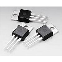
Triacs 600V 4A 33/43V
Manufacturer
Littelfuse Inc
Datasheet
1.Q6008LT.pdf
(6 pages)
Specifications of Q6004LT
Rated Repetitive Off-state Voltage Vdrm
600 V (Min)
Breakover Current Ibo Max
55 A
On-state Rms Current (it Rms)
4 A
Off-state Leakage Current @ Vdrm Idrm
0.05 mA
Gate Trigger Current (igt)
1.2 A
Holding Current (ih Max)
40 mA
Forward Voltage Drop
1.6 V
Mounting Style
Through Hole
Package / Case
TO-220
Breakover Voltage Vbo
43 V
Maximum Operating Temperature
+ 125 C
Minimum Operating Temperature
- 40 C
Off-state Capacitance Co
0.1 uF
Repetitive Peak Forward Blocking Voltage
600 V (Min)
Lead Free Status / RoHS Status
Lead free / RoHS Compliant
Available stocks
Company
Part Number
Manufacturer
Quantity
Price


Data Sheets
Figure E3.7 Maximum Allowable Case Temperature versus
Figure E3.8 Maximum Allowable Case Temperature versus
Figure E3.9 Peak Surge Current versus Surge Current Duration
©2004 Littelfuse, Inc.
Thyristor Product Catalog
200
120
100
130
120
110
100
80
60
50
40
30
20
10
90
80
70
60 0
130
120
110
100
8
6
5
4
3
2
1
90
80
70
60
0
On-state Current (4 A)
On-state Current (6 A to 15 A)
1
0
0
SUPPLY FREQUENCY: 60 Hz Sinusoidal
LOAD: Resistive
RMS ON-STATE CURRENT [I T(RMS) ]: Maximum
Rated Value at Specified Case Temperature
.5
2
2.0
6 A
3 4 5 6 8 10
1.0
4.0
RMS On-state Current [I
RMS On-state Current [I
8 A
Surge Current Duration – Full Cycles
1.5
6.0
2.0
8.0
20
10.0
2.5
4 A
CURRENT WAVEFORM: Sinusoidal
LOAD: Resistive or Inductive
CONDUCTION ANGLE: 360
CASE TEMPERATURE: Measured
as shown on Dimensional Drawings
CURRENT WAVEFORM: Sinusoidal
LOAD: Resistive or Inductive
CONDUCTION ANGLE: 360
CASE TEMPERATURE: Measured
as shown on Dimensional Drawings
3040
T(RMS)
T(RMS)
12.0
3.0
15 A
10 A
60 80 100
14.0
] – Amps
NOTES:
1) Gates control may be lost during
and immediately following surge
current interval.
2) Overload may not be repeated until
junction temperature has returned to
steady state rated value.
] – Amps
3.5
16.0
4.0
200
18.0
300
˚
4.5
˚
20.0
600
5.0
1000
E3 - 5
Figure E3.10 Power Dissipation (Typical) versus On-state Current (4 A)
Figure E3.11 Power Dissipation (Typical) versus On-state Current
Figure E3.12 Normalized diac V
+4
+2
-2
-4
-6
-8
0
4.0
3.0
2.0
1.0
18
16
14
12
10
0
8
6
4
2
0
-40
(6 A to 10 A and 15 A)
0
0
-20
2
Junction Temperature (T
1.0
RMS On-state Current [I
6 A to 10 A
RMS On-state Current [I
0
4
+20 +40 +60 +80 +100 +120 +140
BO
CURRENT WAVEFORM: Sinusoidal
LOAD: Resistive or Inductive
CONDUCTION ANGLE: 360˚
6
2.0
versus Junction Temperature
4 A
CURRENT WAVEFORM: Sinusoidal
LOAD: Resistive or Inductive
CONDUCTION ANGLE: 360 ˚
8
T(RMS)
3.0
T(RMS)
10
] – Amps
http://www.littelfuse.com
] – Amps
15 A
12
J
) – ˚C
4.0
+1 972-580-7777
14
16
5.0
Quadrac
Related parts for Q6004LT
Image
Part Number
Description
Manufacturer
Datasheet
Request
R

Part Number:
Description:
FUSEHOLDER 20A MINI INLINE CRIMP
Manufacturer:
Littelfuse Inc
Datasheet:

Part Number:
Description:
FUSEHOLDER BODY ATO INLINE PNLMT
Manufacturer:
Littelfuse Inc
Datasheet:

Part Number:
Description:
FUSE 2A 63V FAST 1206
Manufacturer:
Littelfuse Inc
Datasheet:
Part Number:
Description:
FUSE 1.25A 63V FAST 1206
Manufacturer:
Littelfuse Inc
Datasheet:
Part Number:
Description:
FUSE .250A 125V FAST 1206
Manufacturer:
Littelfuse Inc
Datasheet:
Part Number:
Description:
FUSE 4A 32V FAST 1206
Manufacturer:
Littelfuse Inc
Datasheet:
Part Number:
Description:
FUSE 1.75A 63V FAST 1206
Manufacturer:
Littelfuse Inc
Datasheet:

Part Number:
Description:
FUSE 1A 32V FST 0603 LEADFREE TR
Manufacturer:
Littelfuse Inc
Datasheet:

Part Number:
Description:
FUSE 1A 32V FAST SLIM 0402
Manufacturer:
Littelfuse Inc
Datasheet:

Part Number:
Description:
FUSE 2A 125V FAST NANO2 SMD
Manufacturer:
Littelfuse Inc
Datasheet:

Part Number:
Description:
FUSE .250A 125V FAST NANO2 SMD
Manufacturer:
Littelfuse Inc
Datasheet:

Part Number:
Description:
FUSE .500A 125V FAST NANO2 SMD
Manufacturer:
Littelfuse Inc
Datasheet:

Part Number:
Description:
FUSE 1.5A 125V FAST NANO2 SMD
Manufacturer:
Littelfuse Inc
Datasheet:

Part Number:
Description:
FUSE 4A 125V FAST NANO2 SMD
Manufacturer:
Littelfuse Inc
Datasheet:

Part Number:
Description:
FUSE 1A 125V FAST NANO2 SMD
Manufacturer:
Littelfuse Inc
Datasheet: