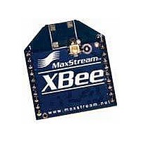
JF1R6-CR3-4I MaxStream, JF1R6-CR3-4I Datasheet - Page 14

JF1R6-CR3-4I
Manufacturer Part Number
JF1R6-CR3-4I
Description
Wireless Accessories 2.4Ghz ant U.FL fem to RPSMA fem cable
Manufacturer
MaxStream
Datasheet
1.XBIB-R.pdf
(72 pages)
Specifications of JF1R6-CR3-4I
Technology/ Type
Cable Assembly
Lead Free Status / RoHS Status
Lead free / RoHS Compliant
For Use With
XBee Modules
XBee/XBee‐PRO™ OEM RF Modules ‐ 802.15.4 ‐ v1.xAx [2007.05.031]
2.2.6. I/O Line Passing
2.2.7. Configuration Example
Virtual wires can be set up between XBee/XBee-PRO Modules. When an RF data packet is received
that contains I/O data, the receiving module can be setup to update any enabled outputs (PWM
and DIO) based on the data it receives.
Note that I/O lines are mapped in pairs. For example: AD0 can only update PWM0 and DI5 can
only update DO5). The default setup is for outputs not to be updated, which results in the I/O data
being sent out the UART (refer to the IU (Enable I/O Output) command). To enable the outputs to
be updated, the IA (I/O Input Address) parameter must be setup with the address of the module
that has the appropriate inputs enabled. This effectively binds the outputs to a particular module’s
input. This does not affect the ability of the module to receive I/O line data from other modules -
only its ability to update enabled outputs. The IA parameter can also be setup to accept I/O data
for output changes from any module by setting the IA parameter to 0xFFFF.
When outputs are changed from their non-active state, the module can be setup to return the out-
put level to it non-active state. The timers are set using the Tn (Dn Output Timer) and PT (PWM
Output Timeout) commands. The timers are reset every time a valid I/O packet (passed IA check)
is received. The IC (Change Detect) and IR (Sample Rate) parameters can be setup to keep the
output set to their active output if the system needs more time than the timers can handle.
Note: DI8 can not be used for I/O line passing.
Applicable Commands: IA (I/O Input Address), Tn (Dn Output Timeout), P0 (PWM0 Configura-
tion), P1 (PWM1 Configuration), M0 (PWM0 Output Level), M1 (PWM1 Output Level), PT (PWM
Output Timeout), RP (RSSSI PWM Timer)
As an example for a simple A/D link, a pair of RF modules could be set as follows:
These settings configure the remote module to sample AD0 and AD1 once each every 20 ms. It
then buffers 5 samples each before sending them back to the base module. The base should then
receive a 32-Byte transmission (20 Bytes data and 12 Bytes framing) every 100 ms.
© 2007 MaxStream, Inc.
Remote Configuration
MY = 0x5678
DL = 0x1234
IR = 0x14
D0 = 2
D1 = 2
IT = 5
IA = 0x5678 (or 0xFFFF)
Base Configuration
DL = 0x5678
MY = 0x1234
P0 = 2
P1 = 2
IU = 1
Chapter 2 ‐ RF Module Operation
14


