PIC-MINI-WEB Olimex Ltd., PIC-MINI-WEB Datasheet
PIC-MINI-WEB
Specifications of PIC-MINI-WEB


Related parts for PIC-MINI-WEB


PIC-MINI-WEB Summary of contents
Page 1
... PIC-MINI-WEB development board Copyright(c) 2010, OLIMEX Ltd, All rights reserved Users Manual Rev. C, July 2006 Page 1 ...
Page 2
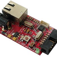
... INTRODUCTION: PIC-MINI-WEB is with dimensions only but don't let this fool you. This board is very powerful and will allow you to connect almost everything to Internet. The board has PIC18F25J10 microcontroller with 32KB of program Flash memory, 1024 RAM memory and allows Microchip free TCP-IP stack to be programmed ...
Page 3
... Power target circuit from MPLAB ICD 2 – this option should be forbidden, you could not select it. Now it is safe to connect the programmer to your target board. PIC-MINI-WEB is tested with MPLAB IDE v.7.62 + MPLAB C18 C compiler possible that the stack might not function properly if used with later versions of MPLAB IDE. ...
Page 4
Secondary oscillator using Timer1 @ 32 kHz - Two-Speed Oscillator Start-up - Fail-Safe Clock Monitor: Allows for safe shutdown if peripheral clock stops o - High-current sink/source 25 mA/25 mA (PORTB and PORTC) - Three programmable external interrupts - ...
Page 5
BLOCK DIAGRAM: Page 5 ...
Page 6
MEMORY MAP: Page 6 ...
Page 7
SCHEMATIC: RJ45 SIDE 180 R8 + 180 R7 3.3V + 100nF 100nF 100nF 100nF Page ...
Page 8
... The board power consumption is: about 180 mA with all peripherals and MCU running at full speed. RESET CIRCUIT: PIC-MINI-WEB reset circuit is made with R12 (10k) pull-up, R13 (330Ω) and capacitor C20 (100nF) and RST button. Manual reset is possible by the RST button. CLOCK CIRCUIT: Quartz crystal 10 MHz is connected to PIC18F25J10 pin 9 (OSC1/CLKIN) and pin 10 clock out (OSC2/CLKOUT) ...
Page 9
... INPUT/OUTPUT: One User button with name BUTTON – connected to PIC18F25J10 pin 21 (PORTB.RB0/INT0/FLT0/AN12); Status green LED connected to PIC18F25J10 pin13 (PORTC.RC2/CCP1). Power supply red LED with name PWR – indicates that external powers source is applied and board power supply is applied; EXTERNAL CONNECTORS DESCRIPTION: ...
Page 10
EXT : Pin # 1 RA0/AN0 3 RA1/AN1 5 RA2/AN2/VREF-/CVREF 7 RA3/AN3/VREF+ 9 RA5/AN4/#SS1/C2OUT 11 VCC +3 GND LAN: Pin # Signal Name Chip Side 1 TPOUT+ 2 TPOUT- 3 3.3V 4 Not Connected (NC) Signal Name Pin ...
Page 11
LED Color Right Yellow Left Green TPOUT- Output Differential signal output. TPOUT+ Output Differential signal output. TPIN- Input Differential signal input. TPIN+ Input Differential signal input. Usage Activity 100MBits/s (Half/Full duplex) Page 11 ...
Page 12
MECHANICAL DIMENSIONS: All measures are in mm. Page 12 ...
Page 13
... AVAILABLE DEMO SOFTWARE : You could find information about PIC-MINI-WEB board, Microchip TCP/IP stack and how to boards on change and configure the software in Understanding PIC-WEB www.olimex.com/dev Page 13 . ...
Page 14
... ORDER CODE: PIC-MINI-WEB – assembled and tested (no kit, no soldering required) How to order? You can order to us directly or by any of our distributors. Check our web All boards produced by Olimex are RoHS compliant Revision history: REV. C www.olimex.com/dev - created July 2006 Page 14 for more info. ...
Page 15
... OLIMEX in good faith. However all warranties implied or expressed including but not limited to implied warranties of merchantability or fitness for purpose are excluded. This document is intended only to assist the reader in the use of the product. OLIMEX Ltd. shall not be liable for any loss or damage arising from the use of any information in this document or any error or omission in such information or any incorrect use of the product ...