MPM-DC-KIT Actel, MPM-DC-KIT Datasheet - Page 2
MPM-DC-KIT
Manufacturer Part Number
MPM-DC-KIT
Description
Power Management Modules & Development Tools Mixed signal Power Manager Kit
Manufacturer
Actel
Type
DC/DC Switching Converters, Regulators & Controllersr
Datasheet
1.MPM-DC-KIT.pdf
(4 pages)
Specifications of MPM-DC-KIT
Input Voltage
1.5 V to 5 V
Output Voltage
0 V to 3.3 V
Interface Type
I2C, JTAG
Operating Supply Voltage
9 V
Product
Power Management Modules
For Use With/related Products
AFS090
Lead Free Status / RoHS Status
Lead free / RoHS Compliant


Connections, Jumper Switches, and Settings
Connect jumpers in the default settings to enable the MPM for SmartFusion design to function
correctly before powering up the boards.
• Jumpers from FB (feedback voltage) of each regulator for voltage trimming
• Jumpers for selection of PWM or SDD (see the MPM User’s Guide for details)
• Push-button switches to disable each regulator and simulate a power failure
Push-button fault injection switches SW8, SW11, SW15, and SW16 ground the enable pin of the
corresponding regulator, thereby injecting failure in the power subsystem. However, this enable pin
is also connected to the pin on the SmartFusion FPGA (MPM_REG1_EN, MPM_REG2_EN,
MPM_REG3_EN, MPM_REG4_EN).The FPGA could be damaged if configured to drive High on
the enable line when the fault injection switch is pressed. To avoid this, Actel recommends that the
FPGA pin driving this enable should be driving Low or tristated.
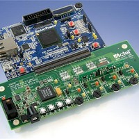
MPM Demo Design Description
The MPM demonstration design takes advantage of the processing power and programmable
flexibility of the SmartFusion™ intelligent mixed signal FPGA on the SmartFusion Evaluation Kit
or Development Kit. Connect either kit to the daughter card and download the software as described
to run the demo.
The daughter card consists of four regulated power supplies running from a 9 V supply.
• National switching regulators for 1.5 V and 3.3 V
• Linear Technology and Artesyn DC-DC regulators for 5 V
Using the MPM design one can do the following:
• Monitor voltage for all rails
• Sequence different power rails for power-up and power-down
• Trim and margin a voltage rails in a closed loop
• Sweep the output voltage (POT circuit to change resistor on feedback voltage)
• Induce failures by disabling the enable input of regulator (push-button to GND enable)
Power sequencing is done by sequentially asserting or deasserting channel enable pins for power-up
and power-down, respectively, and monitoring the associated channel voltage. All enable pins to the
regulator are active high.
– JP12, JP13, JP14, JP15 – Populated with jumper
– JP17, JP18, JP19, JP20 – Connect pins 1-2
– SW8, SW11, SW15, SW16
Mixed Signal Power Manager Daughter Card Kit Quickstart Card
2
Related parts for MPM-DC-KIT
Image
Part Number
Description
Manufacturer
Datasheet
Request
R

Part Number:
Description:
Resistor Network,Thin Film,10KOhms,100WV,.1+/-% Tol,-25,25ppm-TC,1105-Case
Manufacturer:
Vishay
Part Number:
Description:
Resistor Network,Thin Film,10KOhms,100WV,1+/-% Tol,-25,25ppm-TC,1105-Case
Manufacturer:
Vishay

Part Number:
Description:
Compact, 10w Pc Mount Single, Dual & Triple Out Ac/dc Power Supplies
Manufacturer:
MicroPower Direct, LLC
Datasheet:
Part Number:
Description:
Board Mount, 10w Single & Dual Output Ac/dc Power Supplies
Manufacturer:
MicroPower Direct, LLC
Datasheet:
Part Number:
Description:
Ery Low Cost, 10w Compact ?power Brick? Ac/dc Power Supplies
Manufacturer:
MicroPower Direct, LLC
Datasheet:
Part Number:
Description:
Very Low Cost, 10w Compact Power Brick Ac/dc Power Supplies
Manufacturer:
MicroPower Direct, LLC
Datasheet:
Part Number:
Description:
Compact, 15w Pc Mount Single, Dual & Triple Out Ac/dc Power Supplies
Manufacturer:
MicroPower Direct, LLC
Datasheet:
Part Number:
Description:
Board Mount, 15w Single, Dual & Triple Out Ac/dc Power Supplies
Manufacturer:
MicroPower Direct, LLC
Datasheet:
Part Number:
Description:
Chassis Mount, 15w Single, Dual & Triple Out Ac/dc Power Supplies
Manufacturer:
MicroPower Direct, LLC
Datasheet:
Part Number:
Description:
Compact, Board Mount 4w Single And Dual Output Ac/dc Power Supplies
Manufacturer:
MicroPower Direct, LLC
Datasheet:

Part Number:
Description:
MCU, MPU & DSP Development Tools Silicon Sculptor Programming Mod
Manufacturer:
Actel
Part Number:
Description:
MCU, MPU & DSP Development Tools InSystem Programming ProASICPLUS Devices
Manufacturer:
Actel
Part Number:
Description:
Programming Socket Adapters & Emulators PQ160 Module
Manufacturer:
Actel
Part Number:
Description:
Programming Socket Adapters & Emulators Axcelerator Adap Module Kit
Manufacturer:
Actel
Part Number:
Description:
Programming Socket Adapters & Emulators Evaluation
Manufacturer:
Actel