EE-SPY402 Omron, EE-SPY402 Datasheet
EE-SPY402
Specifications of EE-SPY402
Available stocks


Related parts for EE-SPY402


EE-SPY402 Summary of contents
Page 1
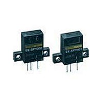
... Appearance Sensing method Sensing distance Diffuse 5 mm Horizontal Vertical J ACCESSORIES Name Solder connector Connector with 1 m cable Connector holder for EE-1003 Output configuration Weight Dark-ON Approx. 2.6 g Light-ON Dark-ON Light-ON Part number EE-1002 EE-1003 EE-1003A Part number EE-SPY301 EE-SPY401 EE-SPY302 EE-SPY402 ...
Page 2
... Shock resistance Destruction: 500 m/s Cable length 2 m max. with a thickness of 0.3 mm EE-SPY401 EE-SPY302 ) with a residual voltage of 1.0 V max with a residual voltage of 0.4 V max. C OFF ON ON OFF Terminal Arrangement Disk OUT 2 (approx. 50G) for 3 times each and Z directions 2 min. EE-SPY402 OFF ON 2 ...
Page 3
... Reference object: White paper (reflection factor: 90 Sensing area l ( EE-SPY301, EE-SPY401 Reference object: White paper ( mm) Operates (reflection Releases factor: 90 (mm) EE-SPY302, EE-SPY402 Reference object: White paper ( mm) (reflection factor: 90 (mm) J OPERATING/RESET DISTANCE VS. CABLE LENGTH (TYPICAL °C Vcc = 4 4.7 kΩ L Reference object: Thickness: AWG24 White paper ( mm) (A) ...
Page 4
... Light-ON/Dark-ON Operation indicator 1.5 to Load 3 mA (relay) OUT Main ← I circuit C Logic circuit Connect a diode in parallel to the load when an inductive load is connected between + and OUT. J TIMING CHART Light-ON Incident Interrupted ON LIGHT indicator (red) OFF Output ON transistor OFF Load (relay) Operates Releases ...
Page 5
... Dimensions Unit: mm (inch) J EE-SPY301, EE-SPY401 26 (1.02) 7 (0.28 (0.55) (0.79) 6 (0.24) 3(0.12) 7.5 (0.30) (3) 2.5 (0.10) J EE-SPY302, EE-SPY402 26 (1.02) 14 3.5 (0.55) (0.14) 7 (0.28) (0.31) 20 (0.79) 6 (0.24) 3(0.12) 7.5 (0.30) (3) 2.5 (0.10) (0.20 (0.79) 14 (0.55) 8 Sensing face (0.31) 4 (0.16) Operation indicator Two, 3.2 dia. ...
Page 6
... J EE-SPY301 + EE-1003 20 (0.79) 10.7 (0.42) J EE-1003 CONNECTOR 6 21.5 (0.85) 10.7 (0.42) 6 (0.24) 1.2 (0.05) 1,000± EE-1003A CONNECTOR HOLDER 5.7 (0.22) 8 (0.31) 0.75 11 (0.43) (0.03) 5.0 2.5 1.75 (0.20) (0.10) (0.07) 4.9 (0.19) 1.0 (0.04) 3±1 Two, 3.2 dia. ...
Page 7
... A capacitance of OUT 10 µF min max Do not solder the cable to the connectors. Use the EE-1002 Connector or EE-1003 Connector (with a 1-m cable attached) to connect the cable to the output terminals. Use the EE1003A Connector Holder to prevent accidental disconnection of the EE-1003 Connector from the EE-SPY301/401/302/402 Photomicrosensor. ...