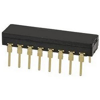
ILQ615-3 Vishay, ILQ615-3 Datasheet

ILQ615-3
Specifications of ILQ615-3
Available stocks
Related parts for ILQ615-3
ILQ615-3 Summary of contents
Page 1
... Because of guaranteed maximum non-saturated and saturated switching characteristics, the ILD615/ILQ615 can be used in medium speed data I/O and control systems. The binned min./max. CTR specification allow easy worst case interface calculations for both level detection and switching applications ...
Page 2
... ILQ615-4 ILD615-1X007 ILD615-2X006 ILD615-2X009 ILD615-3X006 ILD615-3X007 ILD615-3X009 ILD615-4X006 ILD615-4X009 ILQ615-1X009 ILQ615-2X007 ILQ615-3X006 ILQ615-3X009 ILQ615-4X007 ILQ615-4X009 Note For additional information on the available options refer to option information. ABSOLUTE MAXIMUM RATINGS PARAMETER INPUT Reverse voltage Forward current Surge current Power dissipation Derate linearly from 25 °C ...
Page 3
... ABSOLUTE MAXIMUM RATINGS PARAMETER COUPLER Storage temperature Operating temperature Junction temperature (2) Soldering temperature Package power dissipation ILD615 Derate linearly from 25 °C Package power dissipation ILQ615 Derate linearly from 25 °C Isolation test voltage Creepage distance Clearance distance Isolation resistance Notes ( °C, unless otherwise specified. ...
Page 4
... V CE ILD615-3 CTR ILQ615-3 ILD615-4 CTR ILQ615-4 PART SYMBOL = 75 Ω Ω Ω Ω Ω Ω Ω ILD615-1 ILQ615-1 ILD615-2 ILQ615-2 = 1.0 kΩ 1.5 V ILD615-3 TH ILQ615-3 ILD615-4 ILQ615-4 MIN. TYP. MAX. 25 CEsat 40 CEsat 60 CEsat 100 CEsat 125 CE 100 150 200 CE 160 200 ...
Page 5
... ILQ615-2 = 1.0 kΩ 1.5 V ILD615-3 TH ILQ615-3 ILD615-4 ILQ615-4 ILD615-1 ILQ615-1 ILD615-2 ILQ615-2 = 1.0 kΩ 1.5 V ILD615-3 TH ILQ615-3 ILD615-4 ILQ615-4 ILD615-1 ILQ615-1 ILD615-2 ILQ615-2 = 1.0 kΩ 1.5 V ILD615-3 TH ILQ615-3 ILD615-4 ILQ615-4 ILD615/ILQ615 Vishay Semiconductors MIN. TYP. MAX 4.6 ...
Page 6
... kHz iild615_01 Fig Non-Saturated Switching Timing www.vishay.com For technical questions, contact: optocoupler.answers@vishay.com 6 Optocoupler, Phototransistor Output (Dual, Quad Channel) PART SYMBOL ILD615-1 ILQ615-1 ILD615-2 ILQ615-2 = 1.0 kΩ 1.5 V ILD615-3 TH ILQ615-3 ILD615-4 ILQ615-4 TEST CONDITION SYMBOL 1.0 kΩ P 1.0 kΩ P ...
Page 7
... For technical questions, contact: optocoupler.answers@vishay.com Rev. 1.5, 20-Dec-07 Optocoupler, Phototransistor Output (Dual, Quad Channel iild615_06 t off t PLH iild615_07 60 80 100 iild615_08 ILD615/ILQ615 Vishay Semiconductors 200 150 100 Ambient Temperature (°C) amb Fig Maximum LED Power Dissipation 1.4 1 °C amb 1 °C 1 ...
Page 8
... ILD615/ILQ615 Vishay Semiconductors 200 150 100 Ambient Temperature (°C) amb iild615_09 Fig Maximum Detector Power Dissipation 1000 Rth = 500 ° 100 10 1 0.1 0 Collector Emitter Voltage (V) CE iild615_10 Fig Maximum Collector Current vs. Collector Voltage 2.0 Normalized to mA 1.5 CTRce(sat 0 NCTRce 1.0 NCTRce(sat) 0 ...
Page 9
... Fig -2, -3, Propagation Delay vs. Collector Load Resistor 1000 80 100 iild615_19 Fig -4, Propagation Delay vs. Collector Load Resistor 4.0 3.5 3.0 2.5 2.0 tpHL 1.5 1.0 100 ILD615/ILQ615 Vishay Semiconductors Vth = 1 tpLH tpHL 1 0 Collector Load Resistor (kΩ Vth = 1.5 V ...
Page 10
... ILD615/ILQ615 Vishay Semiconductors PACKAGE DIMENSIONS in inches (millimeters) 4 0.255 (6.48) 0.268 (6.81) 5 0.379 (9.63) 0.390 (9.91) 0.030 (0.76) 0.045 (1.14) 4° typ. 0.050 (1.27) 0.018 (0.46) 0.022 (0.56) i178006 0.779 (19.77) 0.790 (20.07) 0.030 (0.76) 0.045 (1.14) 4° 0.018 (0.46) 0.022 (0.56) ...
Page 11
... ILD615/ILQ615 Vishay Semiconductors Option 9 0.375 (9.53) 0.395 (10.03 ) 0.300 (7.62) ref. 0.012 (0.30 ) typ. 0.020 (0.51 ) 0.040 (1.02 ) 15° max. 0.315 (8.00) min ...
Page 12
... ILD615/ILQ615 Vishay Semiconductors OZONE DEPLETING SUBSTANCES POLICY STATEMENT It is the policy of Vishay Semiconductor GmbH to 1. Meet all present and future national and international statutory requirements. 2. Regularly and continuously improve the performance of our products, processes, distribution and operating systems with respect to their impact on the health and safety of our employees and the public, as well as their impact on the environment. ...
Page 13
... Vishay disclaims any and all liability arising out of the use or application of any product described herein or of any information provided herein to the maximum extent permitted by law. The product specifications do not expand or otherwise modify Vishay’ ...


