E3T-SL12 Omron, E3T-SL12 Datasheet - Page 16
E3T-SL12
Manufacturer Part Number
E3T-SL12
Description
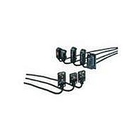
Industrial Photoelectric Sensors NPN CONVERGENT-BEAM
Manufacturer
Omron
Type
Subminiature Photoelectric Sensorr
Series
E3Tr
Specifications of E3T-SL12
Features
Offered in both flat and rectangular
Sensing Method
Limited Reflective
Sensing Distance
5 mm to 15 mm
Light Source
Red LED
Connection
Pre-leaded
Output Configuration
NPN
Output Current
50mA
Sensor Output
NPN DO
Supply Voltage Range Dc
12V To 24V
Sensor Housing
Rectangular
Sensor Input
Optical
Output Type
Transistor
Sensing Range Max
15mm
Switch Terminals
Cable
Sensing Object
White Paper
Sensing Light
Red
Mounting Type
Bracket Mount
Current - Supply
20mA
Voltage - Supply
12 V ~ 24 V
Package / Case
Module, Pre-Wired
Lead Free Status / RoHS Status
Lead free / RoHS Compliant
Lead Free Status / RoHS Status
Lead free / RoHS Compliant, Lead free / RoHS Compliant
Available stocks
Company
Part Number
Manufacturer
Quantity
Price
Company:

Part Number:
E3T-SL12
Manufacturer:
OMRON
Quantity:
336


E3T
Precautions
J AVOID DAMAGE TO THE E3T
•
•
•
J OPERATING ENVIRONMENT
To avoid malfunction, DO NOT install the E3T in the following
environments:
•
•
•
•
J HIGH-TENSION LINES
To avoid Sensor damage or malfunctioning due to induction
noise, do not place the power supply lines of the Photoelectric
Sensor within the same conduit as power lines or high-tension
lines.
J CABLE
The cable can be extended up to 100 m provided that cable
thickness does not exceed the 0.3 mm
J POWER SUPPLIES
If a switching regulator is connected to the E3T, you must ground
the FG (frame ground) and G (ground) terminals, or the switching
noise of the switching regulator may cause the E3T to
malfunction.
J WATER RESISTANCE
•
•
Cat. No. E262-E3-3
1-800-55-OMRON
OMRON ELECTRONICS LLC
One East Commerce Drive
Schaumburg, IL 60173
Avoid damage to the E3T: NEVER apply AC power to the E3T.
Do not exceed the rated voltage on the E3T.
Do not short-circuit the load connected to the E3T.
When supplying power to the E3T, make sure that the
polarity of the power is correct.
Locations where the E3T is exposed to intense sunlight.
Locations with high humidity and where condensation may
result.
Locations with corrosive gas.
Locations with vibration or shock affecting the E3T.
Do not use the E3T underwater, outdoors, or in the rain.
Use M2 screws and washers to mount the E3T. When
mounting the E3T, NEVER strike the E3T with a hammer, or
the E3T will lose its watertight properties.
!
NOTE: DIMENSIONS SHOWN ARE IN MILLIMETERS. To convert millimeters to inches divide by 25.4.
Caution
R
1/02
2
maximum.
OMRON ON- -LINE
Global -- http://www.omron.com
USA -- http://www.omron.com/oei
Canada -- http://www.omron.com/oci
Specifications subject to change without notice.
Be sure to use the E3T within the stable operating range.
J LOAD SHORT-CIRCUIT PROTECTION
The E3T incorporates a load short-circuit protection function. If
the load short-circuits, the output of the E3T will be turned OFF.
Recheck the wiring and turn on the E3T again to reset the load
short-circuit protection function. The load short-circuit protection
function will work if there is a current flow that is 2.4 times larger
than the rated load current.
When using an inductance load, be sure that the inrush current
will not exceed 2.4 times larger than the rated current.
J CLEANING
DO NOT apply paint thinner when cleaning the E3T. Paint thinner
will damage the casing of the E3T.
J INDICATORS
The following graphs indicate the status of each operation level.
J TURNING ON POWER SUPPLY
•
•
Stable
operation
range
Unstable
operation
range
Stable
operation
range
Note:
The E3T will be ready for sensing 100 ms after the power is
turned ON.
If the E3T is connected to a power source different from one
for loads, be sure to turn ON the power supply to the E3T
first.
When the E3T’s operation level is set to the stable
operation range, the E3T will be in its most reliable
operation without being influenced by temperature,
voltage fluctuation, dust, or mounting changes.
Operation
level x 1.2
Operation
level
Operation
level x 0.8
Stability
indicator
(green)
OFF
ON
ON
OMRON CANADA, INC.
416-286-6465
885 Milner Avenue
Scarborough, Ontario M1B 5V8
Operation indicator (orange)
E3T-jjj1
E3T-jjj3
ON
OFF
E3T-jjj2
E3T-jjj4
Printed in U.S.A.
ON
OFF
E3T
Related parts for E3T-SL12
Image
Part Number
Description
Manufacturer
Datasheet
Request
R

Part Number:
Description:
PHOTO MINI S/V THRU PNP LO
Manufacturer:
Omron
Datasheet:
Part Number:
Description:
PHOTO MINI S/V THRU PNP DO
Manufacturer:
Omron
Datasheet:
Part Number:
Description:
Industrial Photoelectric Sensors Photo Mini S/V Conve PNP LO
Manufacturer:
Omron
Datasheet:
Part Number:
Description:
PHOTO MINI S/V CONVER PNP LO
Manufacturer:
Omron
Datasheet:
Part Number:
Description:
Photoelectric Sensors - Industrial PHOTO MINI S/V CONVER PNP DO
Manufacturer:
Omron
Datasheet:
Part Number:
Description:
PHOTO MINI S/V CONVER PNP DO
Manufacturer:
Omron
Datasheet:

Part Number:
Description:
PHOTO MINI S/V CONVER PNP LO
Manufacturer:
Omron
Datasheet:
Part Number:
Description:
PHOTO MINI S/V CONVER PNP DO
Manufacturer:
Omron
Datasheet:
Part Number:
Description:
PHOTO MINI S/V CONVER PNP LO
Manufacturer:
Omron
Datasheet:
Part Number:
Description:
PHOTO MINI S/V CONVER PNP DO
Manufacturer:
Omron
Datasheet:

Part Number:
Description:
G6S-2GLow Signal Relay
Manufacturer:
Omron Corporation
Datasheet:
Part Number:
Description:
Compact, Low-cost, SSR Switching 5 to 20 A
Manufacturer:
Omron Corporation
Datasheet:
Part Number:
Description:
Manufacturer:
Omron Corporation
Datasheet: