TSOP6236TR Vishay, TSOP6236TR Datasheet - Page 5
TSOP6236TR
Manufacturer Part Number
TSOP6236TR
Description
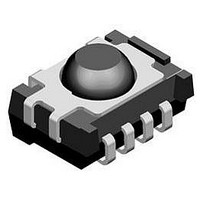
Infrared Receivers 4.5-5.5V 36kHz
Manufacturer
Vishay
Datasheet
1.TSOP6238TR.pdf
(12 pages)
Specifications of TSOP6236TR
Carrier Frequency
36 KHz
Supply Current
0.85 mA
Beam Angle
50 deg
Data Transmission Rate
800 bits/s
Mounting Style
SMD/SMT
Transmission Distance
40 m
Viewing Angle
50 deg
Output Current
5 mA
Operating Voltage
2.7 V to 5.5 V
Power Dissipation
10 mW
Maximum Operating Temperature
+ 85 C
Minimum Operating Temperature
- 25 C
Package / Case
SMD
Transmission Range
40m
Directivity
50°
Supply Voltage Range
2.7V To 5.5V
Opto Case Style
SMD
Operating Temperature Range
-25°C To +85°C
Package Type
SMD
Operating Supply Voltage (typ)
3.3/5V
Operating Supply Voltage (min)
2.7V
Operating Supply Voltage (max)
5.5V
Mounting
Surface Mount
Pin Count
4
Operating Temperature Classification
Commercial
Svhc
No SVHC (20-Jun-2011)
Rohs Compliant
Yes
Lead Free Status / RoHS Status
Lead free / RoHS Compliant
Lead Free Status / RoHS Status
Lead free / RoHS Compliant, Lead free / RoHS Compliant
Available stocks
Company
Part Number
Manufacturer
Quantity
Price
Company:

Part Number:
TSOP6236TR
Manufacturer:
VISHAY
Quantity:
711


SUITABLE DATA FORMAT
The TSOP62.., TSOP64.. series are designed to suppress
spurious output pulses due to noise or disturbance signals.
Data and disturbance signals can be distinguished by the
devices according to carrier frequency, burst length and
envelope duty cycle. The data signal should be close to the
band-pass center frequency (e.g. 38 kHz) and fulfill the
conditions in the table below.
When a data signal is applied to the TSOP62.., TSOP64.. in
the presence of a disturbance signal, the sensitivity of the
receiver is reduced to insure that no spurious pulses are
present at the output. Some examples of disturbance
signals which are suppressed are:
• DC light (e.g. from tungsten bulb or sunlight)
• Continuous signals at any frequency
• Strongly or weakly modulated noise from fluorescent
Note
• For data formats with short bursts please see the datasheet of TSOP61.., TSOP63..
Document Number: 82177
Rev. 2.3, 04-Feb-11
Minimum burst length
After each burst of length
a minimum gap time is required of
For bursts greater than
a minimum gap time in the data stream is needed of
Maximum number of continuous short bursts/second
Recommended for NEC code
Recommended for RC5/RC6 code
Recommended for Sony code
Recommended for Thomson 56 kHz code
Recommended for Mitsubishi code (38 kHz, preburst 8 ms, 16 bit)
Recommended for Sharp code
Suppression of interference from fluorescent lamps
lamps with electronic ballasts (see figure 14 or figure 15)
IR Receiver Modules for Remote
Control Systems
Most common disturbance
signals are suppressed
> 4 x burst length
10 cycles/burst
10 to 70 cycles
12 cycles
16920
16921
TSOP62..
70 cycles
Fig. 14 - IR Signal from Fluorescent Lamp
Fig. 15 - IR Signal from Fluorescent Lamp
800
yes
yes
yes
yes
yes
yes
0
0
with High Modulation
with Low Modulation
TSOP62.., TSOP64..
Vishay Semiconductors
5
5
Time (ms)
Time (ms)
10
10
Even extreme disturbance
signals are suppressed
> 10 x burst length
10 cycles/burst
10 to 35 cycles
12 cycles
15
15
TSOP64..
35 cycles
1300
yes
yes
yes
yes
yes
no
www.vishay.com
20
20
5
Related parts for TSOP6236TR
Image
Part Number
Description
Manufacturer
Datasheet
Request
R

Part Number:
Description:
Ir Receiver Modules For Remote Control Systems
Manufacturer:
Vishay
Datasheet:

Part Number:
Description:
TSOP 48/I�/8GX8 NAND FLASH PLASTIC IND TEMP PBF TSOP 3.3V ASYNCH/PAGE READ
Manufacturer:
Micron Semiconductor Products
Part Number:
Description:
TSOP 66/I�/64MX16 DDR SDRAM PLASTIC PBF TSOP 2.5V
Manufacturer:
Micron Semiconductor Products
Datasheet:
Part Number:
Description:
TSOP 54/I�/256MB 16MX16 SDRAM PLASTIC IND TEMP TSOP 3.3V
Manufacturer:
Micron Semiconductor Products
Datasheet:

Part Number:
Description:
TSOP/16MX16 SDRAM PLASTIC PBF TSOP 3.3V 200MHZ
Manufacturer:
Hynix Semiconductor
Part Number:
Description:
TSOP/16MX16 SDRAM PLASTIC PBF TSOP 3.3V 200MHZ
Manufacturer:
Hynix Semiconductor
Datasheet:
Part Number:
Description:
TSOP 66/C�/64MX8 DDR SDRAM PLASTIC PBF TSOP 2.6V tape and reel
Manufacturer:
Hynix Semiconductor

Part Number:
Description:
TSOP-1 48 12X20 CUSTD FLASH
Manufacturer:
NUMONYX
Datasheet:

Part Number:
Description:
TSOP, IND TEMP, GREEN(DATA FLASH)
Manufacturer:
ATMEL Corporation

Part Number:
Description:
Manufacturer:
Infineon Technologies
Datasheet:
Part Number:
Description:
Manufacturer:
Infineon Technologies
Datasheet:
Part Number:
Description:
Manufacturer:
Infineon Technologies
Datasheet:
Part Number:
Description:
Manufacturer:
Infineon Technologies
Datasheet: