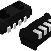
TSOP75338WTR Vishay, TSOP75338WTR Datasheet

TSOP75338WTR
Specifications of TSOP75338WTR
Available stocks
Related parts for TSOP75338WTR
TSOP75338WTR Summary of contents
Page 1
... AGC pass dulator PIN Control circuit 20445-1 ** Please see document “Vishay Material Category Policy”: Document Number: 81997 Rev. 1.5, 24-Mar-11 THE PRODUCT DESCRIBED HEREIN AND THIS DATASHEET ARE SUBJECT TO SPECIFIC DISCLAIMERS, SET FORTH AT TSOP753..W, TSOP755..W FEATURES • Very low supply current • ...
Page 2
... TSOP753..W, TSOP755..W Vishay Semiconductors ABSOLUTE MAXIMUM RATINGS PARAMETER Supply voltage Supply current Output voltage Output current Junction temperature Storage temperature range Operating temperature range Power consumption Note • Stresses beyond those listed under “Absolute Maximum Ratings” may cause permanent damage to the device. This is a stress rating only and functional operation of the device at these or any other conditions beyond those indicated in the operational sections of this specification is not implied ...
Page 3
... Fig Sensitivity vs. Electric Field Disturbances This datasheet is subject to change without notice. Vishay Semiconductors Correlation with Ambient Light Sources: 10 W/m² = 1.4 kLx (Std. illum 2855 K) 10 W/m² = 8.2 kLx (Daylight 5900 K) Wavelength of Ambient Illumination: λ = 950 nm 0.1 ...
Page 4
... TSOP753..W, TSOP755..W Vishay Semiconductors 1 0 kHz mW/m² e 0.8 0.7 0.6 0.5 0.4 0.3 TSOP753..W 0.2 0.1 TSOP755.. 22183-1 Burst Length (number of cycles/burst) Fig Max. Envelope Duty Cycle vs. Burst Length 0.6 0.5 0.4 0.3 0.2 0 Ambient Temperature (°C) 21587 amb Fig Sensitivity vs. Ambient Temperature 1 0 ...
Page 5
... Fig Signal from Fluorescent Lamp TSOP753..W 6 cycles/burst cycles 10 cycles 35 cycles > burst length 2000 yes yes no yes yes yes Most common disturbance signals are suppressed This datasheet is subject to change without notice. Vishay Semiconductors Time (ms) with Low Modulation Time (ms) with High Modulation TSOP755..W 6 cycles/burst cycles ...
Page 6
... TSOP753..W, TSOP755..W Vishay Semiconductors PACKAGE DIMENSIONS in millimeters mold residue 0.5 ± 0 Tool separation line Drawing-No.: 6.550-5300.01-4 Issue: 3; 23.03.2011 21582 ASSEMBLY INSTRUCTIONS Reflow Soldering • Reflow soldering must be done within 72 h while stored under a max. temperature of 30 ° after opening the dry pack envelope • ...
Page 7
... VISHAY LEAD (Pb)-FREE REFLOW SOLDER PROFILE 300 250 200 150 100 19800 TAPING VERSION TSOP..TR DIMENSIONS in millimeters Drawing-No.: 9.700-5342.01-4 Issue: 1: 23.03.09 21785 Document Number: 81997 Rev. 1.5, 24-Mar-11 THE PRODUCT DESCRIBED HEREIN AND THIS DATASHEET ARE SUBJECT TO SPECIFIC DISCLAIMERS, SET FORTH AT TSOP753 ...
Page 8
... TSOP753..W, TSOP755..W Vishay Semiconductors TAPING VERSION TSOP..TT DIMENSIONS in millimeters Ø 1.5 Drawing-No.: 9.700-5341.01-4 Issue: 2: 23.03.09 21666 www.vishay.com 8 THE PRODUCT DESCRIBED HEREIN AND THIS DATASHEET ARE SUBJECT TO SPECIFIC DISCLAIMERS, SET FORTH AT IR Receiver Modules for Remote Control Systems 7.1 16 1.75 7.5 Ø 1.5 min. ...
Page 9
... The standard packing units are labeled with standard bar code labels before transported as finished goods to warehouses. The labels are on each packing unit and contain Vishay Semiconductor GmbH specific data. This datasheet is subject to change without notice. Vishay Semiconductors Start min ...
Page 10
... TSOP753..W, TSOP755..W Vishay Semiconductors VISHAY SEMICONDUCTOR GmbH STANDARD BAR CODE PRODUCT LABEL (finished goods) PLAIN WRITING Item-description Item-number Selection-code LOT-/serial-number Data-code Plant-code Quantity Accepted by Packed by Mixed code indicator Origin Long bar code top Item-number Plant-code Sequence-number Quantity Total length Short bar code bottom ...
Page 11
... IR Receiver Modules for Remote Control Systems VISHAY SEMICONDUCTORS STANDARD BAR CODE LABELS The Vishay Semiconductors standard bar code labels are printed at final packing areas. The labels are on each packing unit and contain Vishay Semiconductors specific data. BAR CODE PRODUCT LABEL (example) 22178 This datasheet is subject to change without notice ...
Page 12
... Vishay product could result in personal injury or death. Customers using or selling Vishay products not expressly indicated for use in such applications their own risk and agree to fully indemnify and hold Vishay and its distributors harmless from and against any and all claims, liabilities, expenses and damages arising or resulting in connection with such use or sale, including attorneys fees, even if such claim alleges that Vishay or its distributor was negligent regarding the design or manufacture of the part ...


