PIC18F26K22-I/SO Microchip Technology, PIC18F26K22-I/SO Datasheet - Page 62
PIC18F26K22-I/SO
Manufacturer Part Number
PIC18F26K22-I/SO
Description
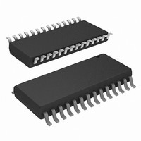
IC PIC MCU 64KB FLASH 28SOIC
Manufacturer
Microchip Technology
Series
PIC® XLP™ 18Fr
Datasheets
1.PIC16F722-ISS.pdf
(8 pages)
2.PIC18F26J13-ISS.pdf
(496 pages)
3.PIC18F24K22-ISP.pdf
(494 pages)
Specifications of PIC18F26K22-I/SO
Core Size
8-Bit
Program Memory Size
64KB (32K x 16)
Core Processor
PIC
Speed
64MHz
Connectivity
I²C, SPI, UART/USART
Peripherals
Brown-out Detect/Reset, HLVD, POR, PWM, WDT
Number Of I /o
24
Program Memory Type
FLASH
Eeprom Size
1K x 8
Ram Size
3.8K x 8
Voltage - Supply (vcc/vdd)
1.8 V ~ 5.5 V
Data Converters
A/D 19x10b
Oscillator Type
Internal
Operating Temperature
-40°C ~ 85°C
Package / Case
28-SOIC (0.300", 7.50mm Width)
Controller Family/series
PIC18
No. Of I/o's
25
Eeprom Memory Size
1KB
Ram Memory Size
3896Byte
Cpu Speed
64MHz
No. Of Timers
7
Processor Series
PIC18F
Core
PIC
Lead Free Status / RoHS Status
Lead free / RoHS Compliant
Lead Free Status / RoHS Status
Lead free / RoHS Compliant
Available stocks
Company
Part Number
Manufacturer
Quantity
Price
Company:

Part Number:
PIC18F26K22-I/SO
Manufacturer:
NXP
Quantity:
928
Part Number:
PIC18F26K22-I/SO
Manufacturer:
MICROCHIP/微芯
Quantity:
20 000


PIC18(L)F2X/4XK22
4.4
PIC18(L)F2X/4XK22 devices implement a BOR circuit
that provides the user with a number of configuration and
power-saving options. The BOR is controlled by the
BORV<1:0> and BOREN<1:0> bits of the CONFIG2L
Configuration register. There are a total of four BOR
configurations which are summarized in
The BOR threshold is set by the BORV<1:0> bits. If
BOR is enabled (any values of BOREN<1:0>, except
‘00’), any drop of V
T
occur if V
chip will remain in Brown-out Reset until V
above V
If the Power-up Timer is enabled, it will be invoked after
V
Reset for an additional time delay, T
below V
chip will go back into a Brown-out Reset and the
Power-up Timer will be initialized. Once V
above V
additional time delay.
BOR
independently configured. Enabling BOR Reset does
not automatically enable the PWRT.
The BOR circuit has an output that feeds into the POR
circuit and rearms the POR within the operating range
of the BOR. This early rearming of the POR ensures
that the device will remain in Reset in the event that V
falls below the operating range of the BOR circuitry.
4.4.1
When BOR is enabled, the BOR bit always resets to ‘0’
on any BOR or POR event. This makes it difficult to
determine if a BOR event has occurred just by reading
the state of BOR alone. A more reliable method is to
simultaneously check the state of both POR and BOR.
This assumes that the POR and BOR bits are reset to
‘1’ by software immediately after any POR event. If
BOR is ‘0’ while POR is ‘1’, it can be reliably assumed
that a BOR event has occurred.
DS41412D-page 62
BOR
DD
rises above V
will reset the device. A Reset may or may not
and
BOR
BOR
Brown-out Reset (BOR)
BOR
DD
DETECTING BOR
.
while the Power-up Timer is running, the
, the Power-up Timer will execute the
falls below V
the
BOR
Power-on
DD
; it then will keep the chip in
below V
BOR
for less than T
Timer
BOR
PWRT
for greater than
Table
(PWRT)
. If V
4-1.
BOR
DD
DD
DD
drops
. The
rises
rises
Preliminary
are
DD
4.4.2
When BOREN<1:0> = 01, the BOR can be enabled or
disabled by the user in software. This is done with the
SBOREN control bit of the RCON register. Setting
SBOREN enables the BOR to function as previously
described. Clearing SBOREN disables the BOR
entirely. The SBOREN bit operates only in this mode;
otherwise it is read as ‘0’.
Placing the BOR under software control gives the user
the additional flexibility of tailoring the application to the
environment without having to reprogram the device to
change BOR configuration. It also allows the user to
tailor device power consumption in software by
eliminating the incremental current that the BOR
consumes. While the BOR current is typically very small,
it may have some impact in low-power applications.
4.4.3
When BOREN<1:0> = 10, the BOR remains under
hardware
described. Whenever the device enters Sleep mode,
however, the BOR is automatically disabled. When the
device returns to any other operating mode, BOR is
automatically re-enabled.
This mode allows for applications to recover from
brown-out situations, while actively executing code,
when the device requires BOR protection the most. At
the same time, it saves additional power in Sleep mode
by eliminating the small incremental BOR current.
4.4.4
Enabling the BOR also enables the Fixed Voltage
Reference (FVR) when no other peripheral requiring the
FVR is active. The BOR becomes active only after the
FVR stabilizes. Therefore, to ensure BOR protection,
the FVR settling time must be considered when
enabling the BOR in software or when the BOR is
automatically enabled after waking from Sleep. If the
BOR is disabled, in software or by reentering Sleep
before the FVR stabilizes, the BOR circuit will not sense
a BOR condition. The FVRST bit of the VREFCON0
register can be used to determine FVR stability.
Note:
SOFTWARE ENABLED BOR
Even when BOR is under software
control, the BOR Reset voltage level is still
set by the BORV<1:0> Configuration bits.
It cannot be changed by software.
DISABLING BOR IN SLEEP MODE
MINIMUM BOR ENABLE TIME
control
and
2010 Microchip Technology Inc.
operates
as
previously
Related parts for PIC18F26K22-I/SO
Image
Part Number
Description
Manufacturer
Datasheet
Request
R

Part Number:
Description:
Manufacturer:
Microchip Technology Inc.
Datasheet:
Part Number:
Description:
Manufacturer:
Microchip Technology Inc.
Datasheet:
Part Number:
Description:
Manufacturer:
Microchip Technology Inc.
Datasheet:
Part Number:
Description:
Manufacturer:
Microchip Technology Inc.
Datasheet:
Part Number:
Description:
Manufacturer:
Microchip Technology Inc.
Datasheet:
Part Number:
Description:
Manufacturer:
Microchip Technology Inc.
Datasheet:
Part Number:
Description:
Manufacturer:
Microchip Technology Inc.
Datasheet:
Part Number:
Description:
Manufacturer:
Microchip Technology Inc.
Datasheet: