E13-01H Cherry Electrical, E13-01H Datasheet - Page 2
E13-01H
Manufacturer Part Number
E13-01H
Description
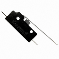
SWITCH LEVER SPST 15A QC TERM
Manufacturer
Cherry Electrical
Series
Er
Type
Single-Pole Snap-Action Switchesr
Datasheet
1.0012-0023.pdf
(3 pages)
Specifications of E13-01H
Circuit
SPST-NO
Switch Function
Off-Mom
Contact Rating @ Voltage
15A @ 125VAC
Actuator Type
Lever, Straight
Mounting Type
Chassis Mount
Termination Style
Quick Connect - .250" (6.3mm)
Operating Force
100gf
Actuator
Roller Lever
Contact Form
SPST - NO
Contact Rating
15 Amps at 125 Volts, 250 Volts
Mounting
Screw
Lead Free Status / RoHS Status
Lead free / RoHS Compliant
Other names
0E13-01H
0E1301H0
CH501
E13-01H0
E1301H
0E1301H0
CH501
E13-01H0
E1301H


Dimensions — Single Pole
Actuator Specifications — Single Pole
Series/
Prefix
E13/G13
E14/E29/E30 –00A
E13/G13
E14/E29/E30
E13/G13
E14/E29/E30
E13/G13
E14/E29/E30
E13/G13
E14/E29/E30
E13/G13
E14/E29/E30
E13/G13
E14/E29/E30
* Measured above reference line. Refer to dimensional drawing above. **Actuator tolerance ±0.031 inches (0.79mm).
† E14, E29 and E30 actuators are shorter and formed up 11° at the button.
*** E30 minimum over- travel is 0.150 (3.81).
Ordering Information
Select the current rating you need.
Combine the corresponding Series/Prefix
number with the appropriate suffix number
for the switch you need.
Specifications subject to change without notice.
†
†
†
†
Actuator
–00M
–00H
–50H
–00K
–50K
Type
–00E
–00J
Switch
Type
Maximum Maximum
Operating Pre-Travel
G13 and E30 have operating point tolerances of ± 0.30.
Force
425
850
425
850
425
850
100
285
170
100
285
211
65
63
(g)
inches (mm)
(13.34)
(10.24)
(12.27)
inches
0.050
(1.27)
0.100
(2.54)
0.050
(1.27)
0.100
(2.54)
0.050
(1.27)
0.100
(2.54)
0.250
(6.35)
0.312
(7.93)
0.343
(8.71)
0.525
0.250
(6.35)
0.348
(8.84)
0.403
0.483
(mm)
0.285±0.020
0.248±0.026
0.670±0.030
(17.02±0.76)
0.633±0.030
(16.08±0.76)
0.812±0.030
(20.63±0.76)
0.775±0.030
(19.69±0.76)
0.312±0.062
0.468±0.062
(11.89±1.57)
0.281±0.062
0.437±0.062
(11.10±1.57)
0.718±0.062
(18.24±1.57)
0.860±0.062
(21.84±1.57)
0.687±0.062
(17.45±1.57)
0.828±0.062
(21.03±1.57)
Mounting — Single Pole
Recommended mounting screw: #6-32
round head. Recommended torque on screw:
6 inch lbs. max. Recommended maximum
torque for ferrule: 20 inch pounds
(7.24±0.51)
(6.30±0.66)
(7.93±1.57)
(7.14±1.57)
Operating
inches
Point*
(mm)
Over-Travel
Minimum Max. Movement Actuation
inches
0.100
(2.54)
0.050
(1.27)
0.108
(2.74)
0.050
(1.27)
0.218
(5.54)
0.168
(4.27)
0.187
(4.75)
0.105 ***
(2.67)
0.187
(4.75)
0.218
(5.54)
0.187
(4.75)
0.130
(3.30)
0.187
(4.75)
0.218
(5.54)
(mm)
Differential
inches
0.015
(0.38)
0.015
(0.38)
0.015
(0.38)
0.015
(0.38)
0.015
(0.38)
0.015
(0.38)
0.093
(2.36)
0.050
(1.27)
0.140
(3.56)
0.080
(2.03)
0.093
(2.36)
0.045
(1.14)
0.093
(2.36)
0.073
(1.85)
(mm)
Length**
(38.10)
(20.85)
(44.45)
(27.20)
(35.33)
(17.47)
(41.28)
(23.95)
1.500
0.821
1.750
1.071
1.391
0.688
1.625
0.943
inches
(mm)
—
—
—
—
—
—
Actuators — Single Pole
Standard type integral hinged lever and
roller actuators are available in choice of
two mounting positions. Actuation lengths
are dimensioned from centerline of switch
mounting hole as shown.
“J” & “M” Type
Optional Hardware — Single Pole
Brass Hex Nut
Brass Knurled Nut
Brass Hex Nut
(Nickel-Plated)
Brass Knurled Nut
(Nickel-Plated)
Star Washer (Lockwasher)
Circuitry — Single Pole
Contact arrangement available in choice of
single pole double throw or single pole sin-
gle throw, either normally open or normally
closed. In general, normally open may be
specified by changing suffix number from
00 to 01 and normally closed by changing
suffix number to 02.
Example: E13-00E is double throw,
E13-01E is normally open, and E13-02E
is normally closed.
Terminals — Single Pole
Standard 0.250 x 0.032 (6.35mm x 0.81mm)
[Optional 0.187 x 0.032 (4.75mm x 0.81mm)]
QC terminals can be furnished with angle
formed up or down. Forms include straight
30°, 45°, 85° up or down. Other forms can
be provided.
0012-0023
0012-0025
0012-0028
0012-0026
0012-0073
49
Related parts for E13-01H
Image
Part Number
Description
Manufacturer
Datasheet
Request
R

Part Number:
Description:
Basic / Snap Action / Limit Switches USE 540-E13-00K
Manufacturer:
Cherry Electrical

Part Number:
Description:
SWITCH SNAP SPDT 15A QC TERM
Manufacturer:
Cherry Electrical
Datasheet:

Part Number:
Description:
SWITCH LEVER SPDT 15A QC TERM
Manufacturer:
Cherry Electrical
Datasheet:

Part Number:
Description:
SWITCH SNAP SPDT 15A QC TERM
Manufacturer:
Cherry Electrical
Datasheet:

Part Number:
Description:
SWITCH ROLLER SPDT 15A QC TERM
Manufacturer:
Cherry Electrical
Datasheet:

Part Number:
Description:
SWITCH SNAP SPST 15A QC TERM
Manufacturer:
Cherry Electrical
Datasheet:

Part Number:
Description:
SWITCH ROLLER SPDT 15A QC TERM
Manufacturer:
Cherry Electrical
Datasheet:

Part Number:
Description:
SWITCH LEVER SPDT 15A QC TERM
Manufacturer:
Cherry Electrical
Datasheet:

Part Number:
Description:
SWITCH SNAP SPDT 15A QC TERM
Manufacturer:
Cherry Electrical
Datasheet:
Part Number:
Description:
Limit Switch,RIGHT ANGLE,SPST,ON-(OFF),QUICK CONNECT Terminal,PUSHBUTTON
Manufacturer:
Cherry Electrical

Part Number:
Description:
MOUSE, LASER WIRELESS IR, USB, BLUE/BLK
Manufacturer:
Cherry Electrical
Datasheet:
Part Number:
Description:
MOUSE, LASER WIRELESS IR, USB, BLUE/BLK
Manufacturer:
Cherry Electrical
Datasheet:
Part Number:
Description:
Manufacturer:
Cherry Electrical
Datasheet:
Part Number:
Description:
Manufacturer:
Cherry Electrical
Datasheet: