44A60-01-1-06N Grayhill Inc, 44A60-01-1-06N Datasheet - Page 9
44A60-01-1-06N
Manufacturer Part Number
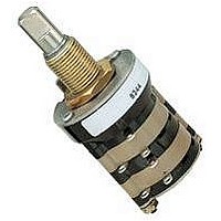
44A60-01-1-06N
Description
SWITCH ROTARY SP-6POS NONSHT
Manufacturer
Grayhill Inc
Series
44r
Datasheet
1.44D30-03-1-AJN.pdf
(10 pages)
Specifications of 44A60-01-1-06N
Angle Of Throw
60°
Number Of Positions
6
Number Of Decks
1
Number Of Poles Per Deck
1
Circuit Per Deck
SP6T
Contact Rating @ Voltage
5A @ 115VAC
Actuator Type
Flatted (6.35mm dia)
Mounting Type
Panel Mount
Termination Style
Solder Lug
Orientation
Vertical
No. Of Poles
1
No. Of Switch Positions
6
Contact Current Ac Max
1A
Contact Current Dc Max
1A
Contact Voltage Ac Max
115V
Contact Voltage Dc Max
115V
Circuitry
SP6T
Lead Free Status / RoHS Status
Lead free / RoHS Compliant
Other names
Q519008


CHOICES AND LIMITATIONS: Series 42, 43, 44 and 54
A = Standard, Solder Lugs
P = Standard, PC Mount Terminals
D = Standard, Adjustable Stops
SINGLE SHAFT SWITCHES
Concentric Shaft Switches
1
instead of number of positions when ordering.
2
of these styles, see Standard Options.
3
positions per pole, continuous rotation is
possible. Specify fixed stop or continuous
rotation when ordering single shaft switches.
Concentric shaft switches have continuous
Rotary
For Adjustable Stop (with the letter D), use AJ
For 45°, 60° or 90° throws in Series 54 switches
For single pole switches with the maximum
30
Series
Series
42
44
44
42
42
54
43
54
43
54
Grayhill, Inc. • 561 Hillgrove Avenue • LaGrange, Illinois
Choices
Style
A
UA
M
D
UD
M
2
2
Unsealed
2
A
UA
UM
M
MB
MG
MBG
H
HB
HG
HBG
D
UD
P
UP
5
Angle of
Throw
Multi-Deck Rotary Switches
Style Choices
30°
36°
30°
36°
30°
Shaft/Panel Seal
01 thru 03
01 thru 03
01 thru 03
01 thru 03
01 thru 03
01 thru 03
01 thru 03
01 thru 03
Decks
S
US
—
MS
MBS
MGS
MBGS
HS
HBS
HGS
HBGS
—
—
SP
USP
4
4
4
4
rotation.
4
qualified but are made of the same materials and
construction as qualified types. For qualified
switches with shaft and panel seal, use equivalent
HS style.
5
and construction as the M style switches. For
military switch UM is not required; use M style.
S = Shaft and Panel Seal
U = UL Recognized
M = Military Qualified 85°C
Styles which include both M and S are not
UM switches are made of the same materials
Poles
1
2
1
1
2
1
1
2
CONCENTRIC SHAFT, 2 SWITCHES
Section A (Front)
Angle of
Throw
36°
30°
45°
60°
90°
30°
36°
36°
ADD-A-POT SWITCHES
02 thru 10
02 thru 12
02 thru 06
AJ (2-12)
AJ (2-6)
AJ (2-10)
02 thru 12
02 thru 06
Position
60525-5997 • USA • Phone: 708-354-1040 • Fax: 708-354-2820 • www.grayhill.com
1
5
1
1
3
5
01 thru 12
01 thru 12
01 thru 12
01 thru 12
01 thru 08
01 thru 06
01 thru 04
01 thru 04
01 thru 12
01 thru 06
01 thru 04
01 thru 03
01 thru 12
01 thru 06
01 thru 04
01 thru 12
01 thru 06
01 thru 12
01 thru 12
01 thru 08
01 thru 06
01 thru 12
01 thru 12
01 thru 12
Number of
4
Decks
N or S
N or S
N or S
N or S
N or S
N or S
N or S
N or S
N or S
01 thru 03
01 thru 03
01 or 02
01
01
01
01 thru 03
01 thru 03
Per Deck
Decks
Poles
1
2
1
2
3
4
5
6
1
2
3
4
1
2
3
1
2
1
2
3
4
1
2
1
H = Military Qualified, 125°C
B = Military, Grounded Shaft
G = Military, Low Level Rating
Second shaft operates a potentiometer
supplied by the customer.
Rear mounting plates are provided.
Poles
Per Pole
02 thru 10
02 thru 05
02 thru 12
02 thru 06
02 thru 04
02 or 03
02
02
02 thru 08
02 thru 04
02
02
02 thru 06
02 or 03
02
02 thru 04
02
AJ (2 thru 12)
AJ (2 thru 6)
AJ (2 thru 4)
AJ (2 or 3)
AJ (2 thru 10)
AJ (2 thru 5)
02 thru 10
Positions
Section B (Rear)
1
2
3
4
5
6
1
2
1,3
02 thru 12
02 thru 06
02 thru 04
02 or 03
02
02
02 thru 10
02 thru 05
3
3
3
3
3
3
1
Position
1
1
1
1
1
Non-Shorting
Shorting or
3
3
N or S
N or S
N or S
N or S
N or S
N or S
N or S
N or S
N or S
N or S
N or S
N or S
N or S
N or S
N or S
N or S
N or S
N
N
N
N
N
N
N
N or S
N or S
N or S
N or S
N or S
N or S
N or S
N or S
N or S
Related parts for 44A60-01-1-06N
Image
Part Number
Description
Manufacturer
Datasheet
Request
R

Part Number:
Description:
Rotary Switch, Standard, Solder Lug, 60°
Manufacturer:
Grayhill Inc
Part Number:
Description:
Rotary Switch, Standard, Solder Lug, 60°
Manufacturer:
Grayhill Inc
Datasheet:
Part Number:
Description:
Rotary Switch, Standard, Solder Lug, 60°
Manufacturer:
Grayhill Inc
Part Number:
Description:
Rotary Switch, Standard, Solder Lug, 60°
Manufacturer:
Grayhill Inc
Part Number:
Description:
Rotary Switch, Standard, Solder Lug, 60°
Manufacturer:
Grayhill Inc
Part Number:
Description:
Rotary Switch, Standard, Solder Lug, 60°
Manufacturer:
Grayhill Inc

Part Number:
Description:
Rotary Switch, Standard, Solder Lug, 60°
Manufacturer:
Grayhill Inc
Datasheet:
Part Number:
Description:
44A60-06-2-03N R Lug, 60°
Manufacturer:
Grayhill Inc
Datasheet:
Part Number:
Description:
44A60-08-1-06N-C R Lug, 60°
Manufacturer:
Grayhill Inc
Datasheet:
Part Number:
Description:
44A60-10-1-05N R Lug, 60°
Manufacturer:
Grayhill Inc
Datasheet:
Part Number:
Description:
44A60-12-1-06N-C R Lug, 60°
Manufacturer:
Grayhill Inc
Datasheet:
Part Number:
Description:
Rotary Switch, Standard, Solder Lug, 60°
Manufacturer:
Grayhill Inc
Part Number:
Description:
Rotary Switch, Standard, Solder Lug, 60°
Manufacturer:
Grayhill Inc
Part Number:
Description:
Rotary Switch, Standard, Solder Lug, 60°
Manufacturer:
Grayhill Inc